Rotating fluid jet with improved rotary seal

a technology of rotating fluid and seals, which is applied in the direction of engine seals, adjustable joints, pipe joints, etc., can solve the problems of seals failing earlier and high temperature levels on seals, and achieve the effect of reducing heat generation, reducing total force, and small area

Active Publication Date: 2009-10-13
NEW LANTAO BUS
View PDF12 Cites 13 Cited by
  • Summary
  • Abstract
  • Description
  • Claims
  • Application Information

AI Technical Summary

Benefits of technology

[0005]With this arrangement, the force on the seal is over a much smaller area, and the total force is thus reduced. The amount of heat generated is reduced, and consequently the life of the seal is increased significantly.

Problems solved by technology

This relatively large area causes high temperature levels on the seal, and results in seals failing earlier than would be desirable.

Method used


Image

  • Rotating fluid jet with improved rotary seal
  • Rotating fluid jet with improved rotary seal
  • Rotating fluid jet with improved rotary seal

Examples


Embodiment Construction

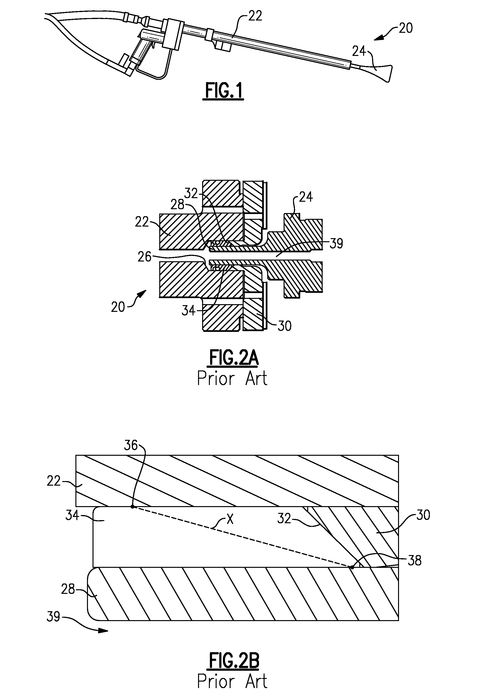
[0013]A cleaning lance 20 is illustrated in FIG. 1. As known, the cleaning lance 20 is hand held and has a stationary housing 22 mounting a rotating nozzle 24. High pressure fluid, and typically water, jets outwardly of the nozzle and against the surface to be cleaned. While this lance is shown, it should be understood that the present application would extend to other types of systems for jetting fluids, and for any system having a rotating nozzle. As one example only, the invention extends to robotic mounted for fluid cleaning structures.

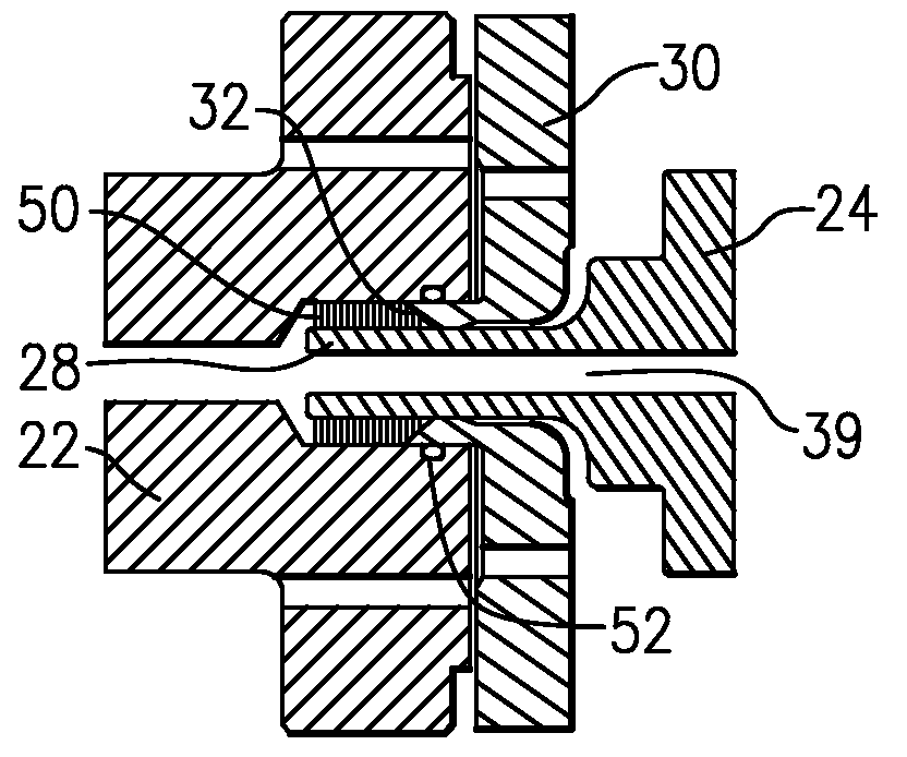
[0014]As shown in FIG. 2A, the nozzle 24 is received within the housing 20. An inner cavity 26 in the housing receives a shaft end 28 from the nozzle 24. A back-up ring 30 is secured to the housing 22, and has an angled end face 32 abutting a surface of the seal 34.

[0015]As shown in FIG. 2B, the seal 34 creates an outer seal point 36 and an inner seal point 38. The outer seal point 36 is on the housing 22, and the inner seal point 38 is on the sha...


PUM


Abstract

An improved seal for use in fluid systems such as a water jet system includes an outer seal point that is very close to an inner seal point. By spacing these two seal points very close together, the force on the seal is greatly reduced compared to the prior art. In the disclosed embodiment, the outer seal point is on an angled forward face of the seal that abuts a back-up ring angled face. The inner seal point is between the seal and an internal shaft which rotates relative to a housing.

Description

BACKGROUND OF THE INVENTION[0001]This application relates to an improved seal for use at a rotating nozzle to housing interface in systems such as high pressure water jetting systems.[0002]High pressure water jetting systems are known, and are used to apply very high pressure water against surfaces to be cleaned. In such systems, a hand-held lance or a robot mounted cleaning member has a housing that mounts a rotating nozzle. The nozzle has a plurality of jets at an angle relative to a rotational axis of the nozzle. As high pressure water is delivered outwardly of the jets, forces on the nozzle cause it to rotate within the housing.[0003]In the prior art, a seal between the housing and a shaft of the nozzle has a sealing surface at both radially outer and radially inner surfaces. The radial inner surface was typically on the shaft and the radially outer surface was within the housing. These two sealing points at those locations creates a force on the seal over a relatively large are...

Claims


Application Information

Patent Timeline
Patent Type & Authority Patents(United States)
IPC IPC(8): B05B3/06
CPCB05B3/06F16L27/0808F16J15/184F16J15/166Y10S239/04
Inventor TRUNICK, DANIEL D.HERHOLD, MATTHEW O.
Owner NEW LANTAO BUS
Why Eureka
Try Eureka