Shaft coupling, and function unit drive device for an image forming device comprising the same

a technology of shaft coupling and drive device, which is applied in the direction of rod connection, corona discharge, instruments, etc., can solve the problems of difficult use of shaft coupling b>100/b> in a machine or device, and the size of the entire structure will become enlarged, so as to achieve the effect of suppressing coupling skip and high quality

Inactive Publication Date: 2009-10-13
KYOCERA DOCUMENT SOLUTIONS INC
View PDF6 Cites 92 Cited by
  • Summary
  • Abstract
  • Description
  • Claims
  • Application Information

AI Technical Summary

Benefits of technology

[0018]In the shaft coupling and the device for driving a function unit of the image forming device according to the present invention, a drive coupling and a driven coupling are unlikely to wear due to rattling at the connected portion, thus suppressing coupling skip. As a result, according to the shaft coupling of the present invention, the drive is reliably transmitted from the drive shaft to the driven shaft.
[0019]Furthermore, in the shaft coupling according to the present invention, since the drive coupling and the driven coupling are engaged with each other in concave-convex engagement, the whole structure is made more compact.
[0020]Furthermore, since the device for driving a function unit of the image forming device uses the shaft coupling according to the present invention, the drive is reliably transmitted from the motor, thereby making it possible to print a high quality image.

Problems solved by technology

Therefore, the axial length thereof will lengthen, and the size of the entire structure will become enlarged, thus making it difficult to use the shaft coupling 100 in a machine or device which must be as small as possible, such as an image forming device.
Therefore, if the torque of the driven device is large and the fluctuation of the torque is large, the concave portion 63 and a tip of the convex portion 61 may slide against each other and thereby cause wear.

Method used


Image

  • Shaft coupling, and function unit drive device for an image forming device comprising the same
  • Shaft coupling, and function unit drive device for an image forming device comprising the same
  • Shaft coupling, and function unit drive device for an image forming device comprising the same

Examples


Embodiment Construction

Schematic Structure of the Image Forming Device

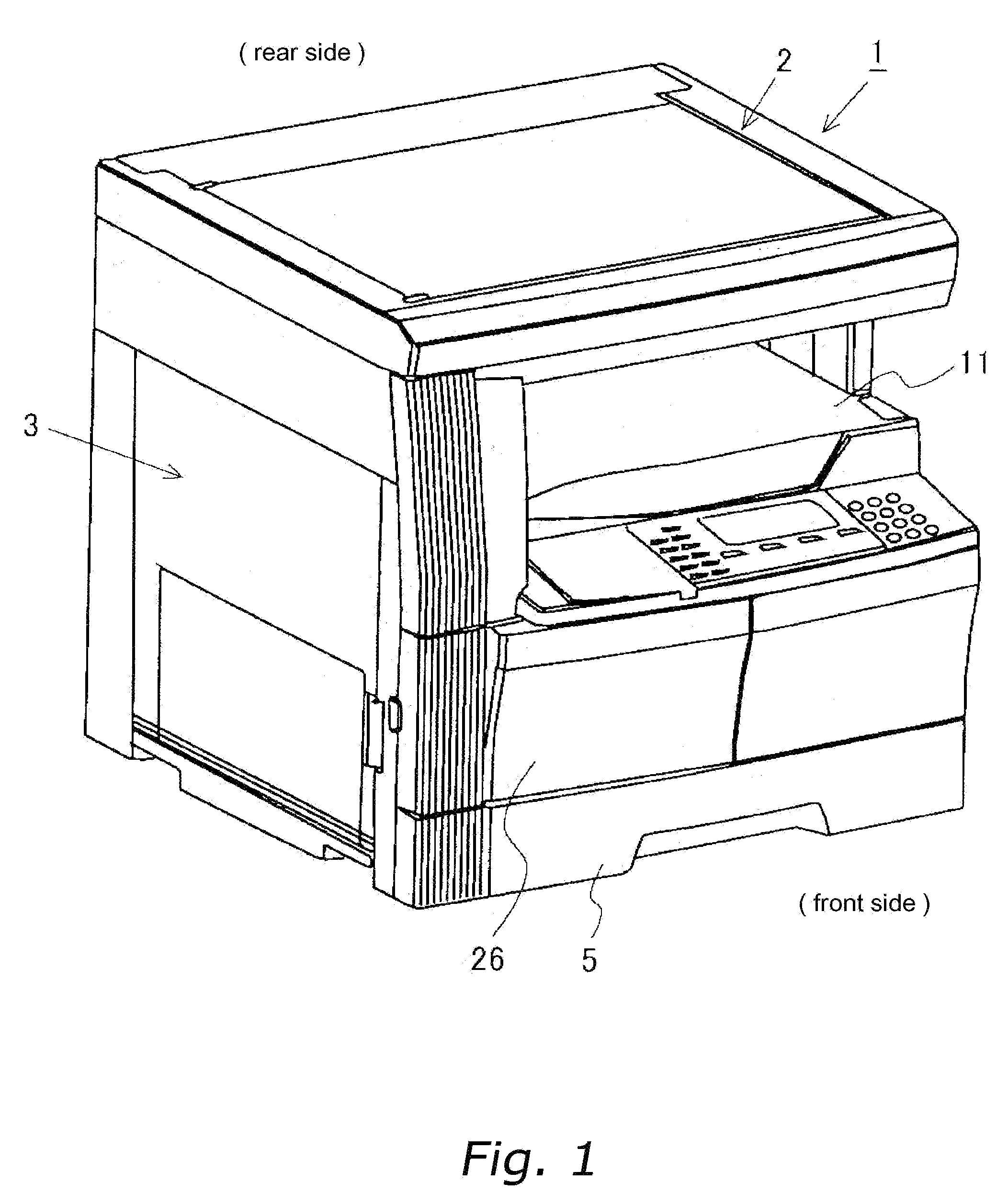
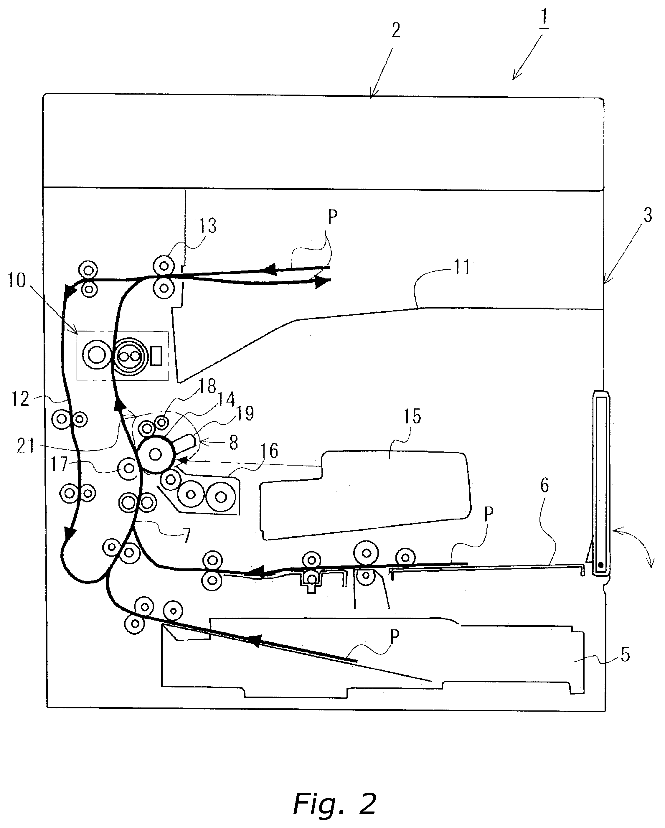
[0041]FIG. 1 and FIG. 2 show a copying machine 1 as an image forming device according to the present invention. FIG. 1 is an external, perspective view of the copying machine 1. FIG. 2 is a view showing the schematic structure of the copying machine 1. As shown in these figures, the copying machine 1 includes a scanner unit 2 for reading an image from an original document, and a printer unit 3 for printing the image data read by the scanner unit 2 onto a recording medium P (such as a sheet of copy paper or plastic film). The printer unit 3 performs the following processes. First, a recording medium P, fed from a paper feed cassette 5 or a manual paper feed tray 6, is conveyed along a conveyance path 7, and then a toner image is transferred by an image forming unit 8 to the recording medium P. Next, the record medium P to which the toner image is transferred is forwarded to a fixing unit 10 in order to fix the toner image onto the record...


PUM


Abstract

Inner circumference projections of a driven coupling are engaged with inner circumference recesses of a drive coupling. Outer circumference projections of the driven coupling are engaged with outer circumference recesses of the drive coupling. A chamfered portion formed at each tip of the rotational leading-side side surface of the inner circumference projections is capable of contact with the leading-side side surface of each inner circumference recess. A rotational trailing-side circumferential end face of each outer circumference projection and a rotational trailing-side circumferential end face of each outer circumference recess are in surface-to-surface contact with each other. As a result, the drive coupling and the driven coupling can rotate integrally without rattling in the rotational direction.

Description

BACKGROUND OF THE INVENTION[0001]1. Field of the Invention[0002]The present invention is related to a shaft coupling, particularly to a shaft coupling for transmitting the drive from a drive shaft to a driven shaft, both the shafts being split coaxially. Furthermore, the present invention is related to a device for driving a function unit of an image forming device, particularly to a device for driving a function unit of an image forming device such as a copying machine, a printer, a facsimile, and a multifunction device that uses the shaft coupling to transmit the drive of a motor to a driven device such as a photoconductor.[0003]2. Background Information[0004]Conventionally, in an image forming device such as a copying machine employing an electrostatic copying system, an image forming unit transfers a toner image to a recording medium, and the recording medium to which the toner image is transferred is sent along a conveyance path to a fixing unit. In the fixing unit, the toner i...

Claims


Application Information

Patent Timeline
Patent Type & Authority Patents(United States)
IPC IPC(8): G03G15/02
CPCG03G15/757Y10T403/7007Y10T403/7013Y10T403/7011Y10T403/7009Y10T403/7005Y10T403/7015
Inventor MARUMOTO, TAKESHI
Owner KYOCERA DOCUMENT SOLUTIONS INC
Why Eureka
Try Eureka