Active wireless tagging system on peel and stick substrate

a technology of active wireless tagging and peeling, applied in the direction of primary cell maintenance/service, secondary cell servicing/maintenance, cell components, etc., can solve the problems of limited tag functionality, power supply that is quite heavy or large, battery capacity must be sufficient, etc., and achieve the effect of extending the scope of tag possible functions

Inactive Publication Date: 2009-10-13
CYMBET CORP
View PDF240 Cites 44 Cited by
  • Summary
  • Abstract
  • Description
  • Claims
  • Application Information

AI Technical Summary

Benefits of technology

[0005]The present invention provides a power source on the tag that lasts the life of the tagged item to allow sensing and communication

Problems solved by technology

This limits the functionality of the tag.
One drawback to using batteries is that batteries must have sufficient capacity to power the device for at least the length of time the device is in use.
Having sufficient battery capacity can result in a power supply that is quite heavy or large compa

Method used


Image

  • Active wireless tagging system on peel and stick substrate
  • Active wireless tagging system on peel and stick substrate
  • Active wireless tagging system on peel and stick substrate

Examples


Embodiment Construction

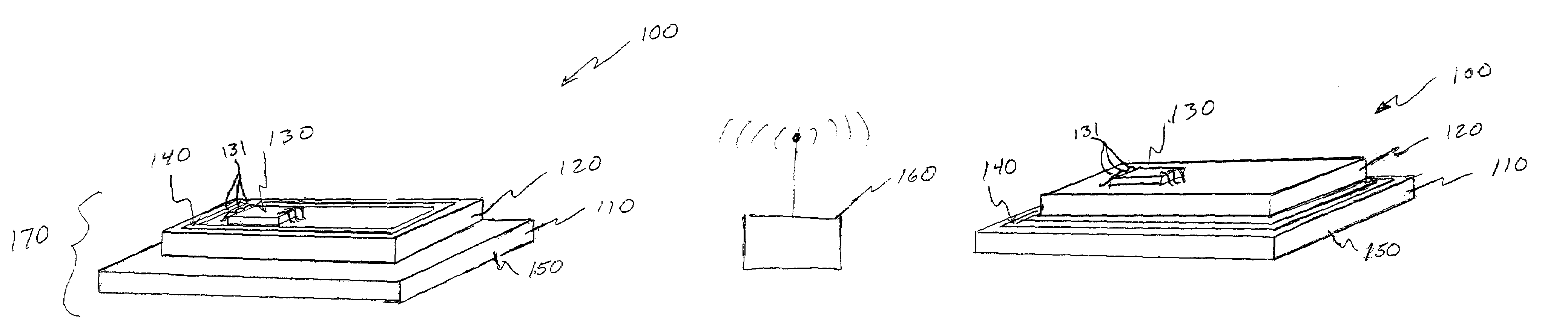
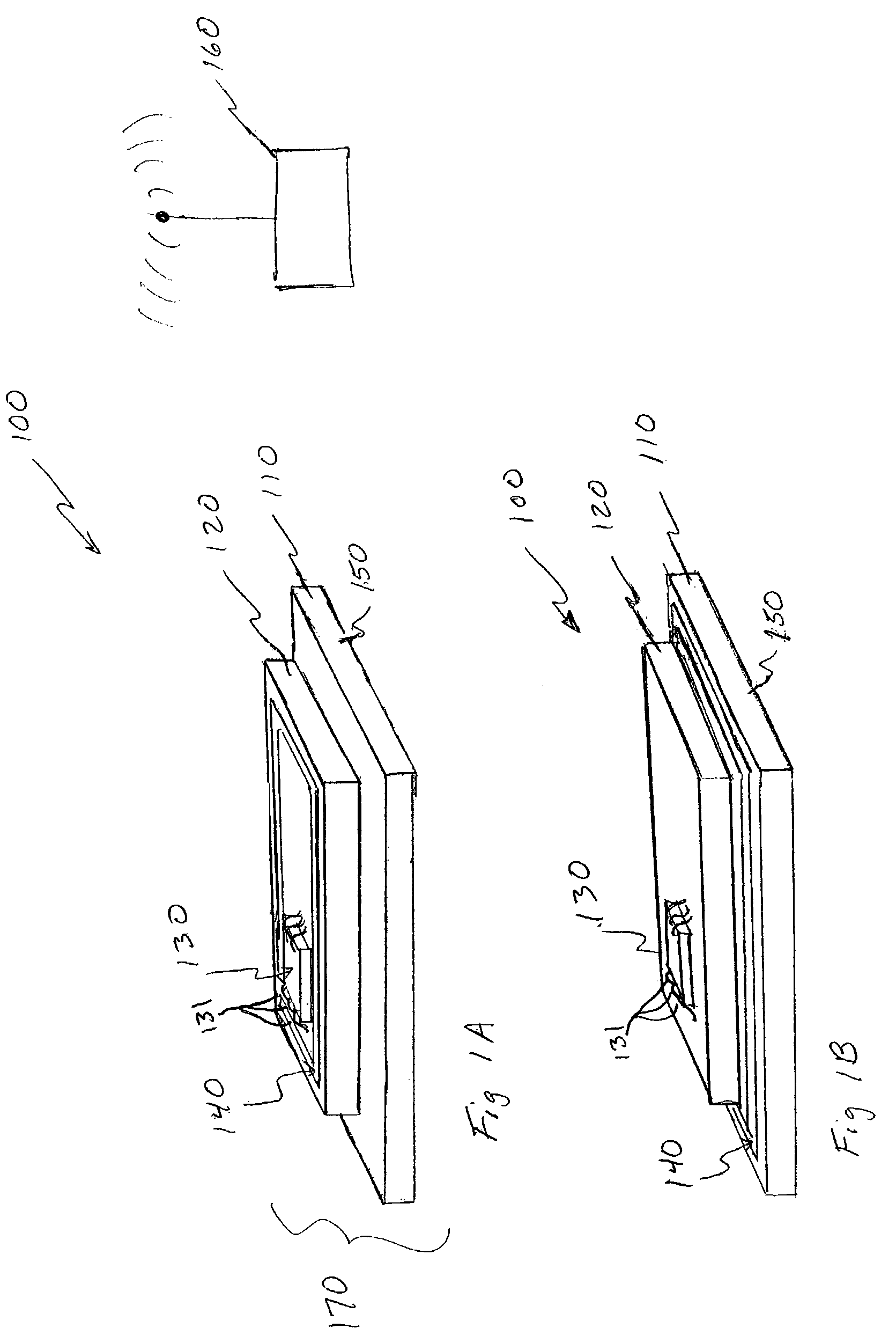
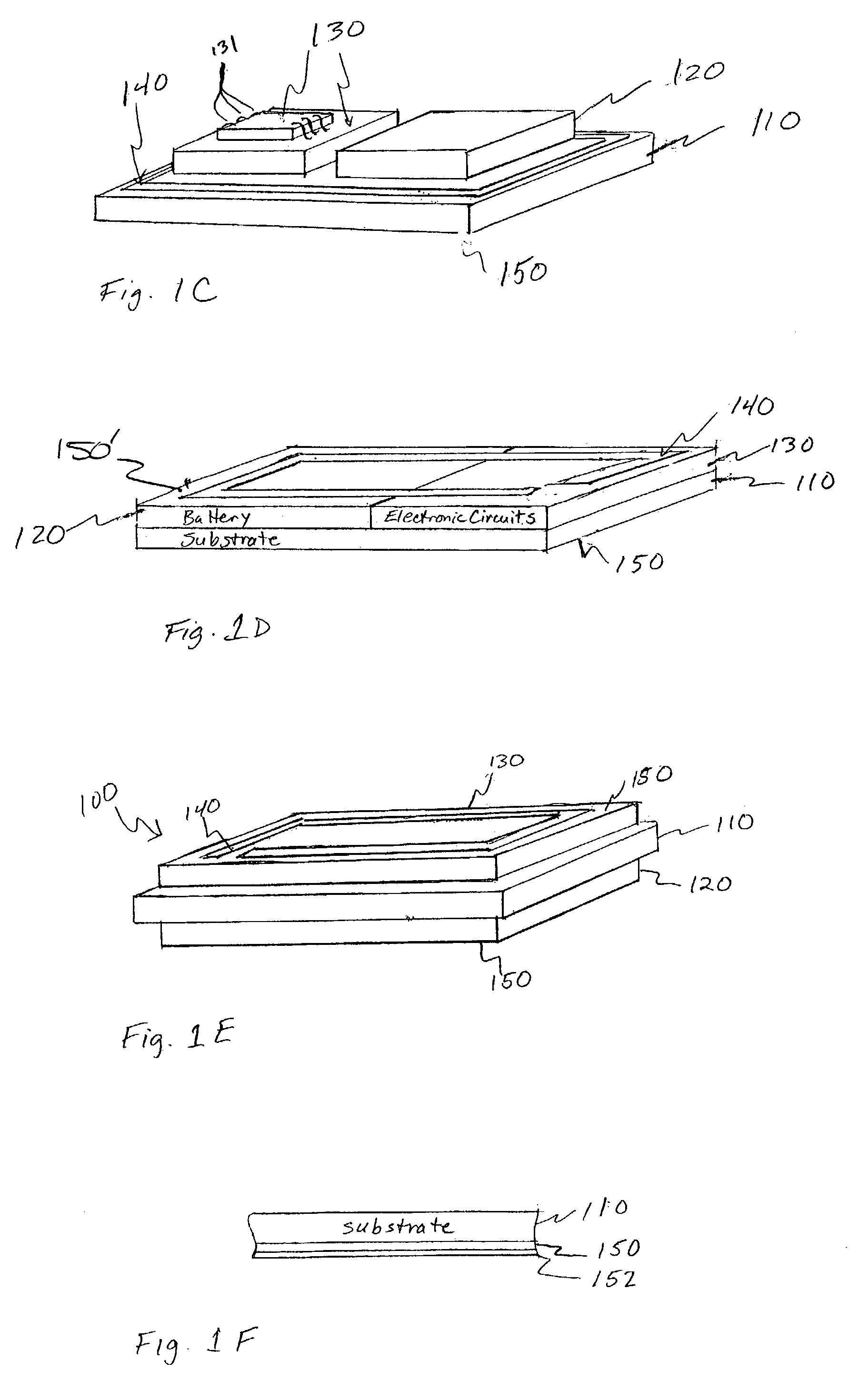
[0034]In the following detailed description of the preferred embodiments, reference is made to the accompanying drawings that form a part hereof, and in which are shown, by way of illustration, specific embodiments in which the invention may be practiced. It is to be understood that other embodiments may be utilized and structural changes may be made without departing from the scope of the present invention.

[0035]It is to be understood that in different embodiments of the invention, each battery in the Figures or the description can be implemented using one or more cells, and if a plurality of cells is implemented, the cells can be wired in parallel or in series. Thus, where a battery or more than one cell is shown or described, other embodiments use a single cell, and where a single cell is shown or described, other embodiments use a battery or more than one cell. Further, the references to relative terms such as top, bottom, upper, lower, and other relative terms refer to an examp...


PUM


Abstract

A radio frequency identification (RFID) device provided on a thin-film battery. A system includes the RFID device in communication with a remote radio frequency (RF) transmitter and/or receiver. In some embodiments, the RFID device of the system includes a flexible substrate, a thin-film battery deposited on the flexible substrate, an electronic circuit placed on the battery and coupled to the battery to provide power, and a Radio Frequency (RF) antenna connected to the electronic circuit. In some embodiments, the battery of the RFID device is a rechargeable battery, and the battery is recharged when energy is transmitted from the remote device. Another aspect of the invention provides a system for making an RFID device.

Description

CROSS-REFERENCES TO RELATED INVENTIONS[0001]This invention is related to U.S. patent application Ser. No. 09 / 816,602 (now U.S. Pat. No. 6,986,965) titled “Device Enclosures with Integrated Batteries” filed Mar. 23, 2001, U.S. patent application Ser. No. 09 / 815,884 (now U.S. Pat. No. 7,433,655) titled “Battery-Operated Wireless-Communication Apparatus and Method,” filed Mar. 23, 2001, U.S. patent application Ser. No. 10 / 336,620 (now U.S. Pat. No. 6,906,436) titled “Solid State Activity-Activated Battery Device and Method” filed on even date herewith, U.S. patent application Ser. No. 10 / 336,621 (now U.S. Pat. No. 7,294,209) titled “APPARATUS AND METHOD FOR DEPOSITING MATERIAL ONTO A SUBSTRATE USING A ROLL-TO-ROLL MASK” filed on even date herewith, and U.S. patent application Ser. No. 10 / 336,619 (now abandoned) titled “APPARATUS AND METHOD FOR DEPOSITING MATERIAL ONTO MULTIPLE INDEPENDENTLY MOVING SUBSTRATES IN A CHAMBER” filed on even date herewith, each of which is incorporated by re...

Claims


Application Information

Patent Timeline
IPC IPC(8): H04B1/38H04M1/00H01M6/40H01M6/50H01M10/00H01M10/42H01M10/46H01M50/119H01M50/121
CPCH01M2/0267H01M2/0275H01M6/40H01M10/46H01M10/42H01M10/4257H01M6/5066Y02E60/10H01M50/121H01M50/119
Inventor JENSON, MARK L.KLAASSEN, JODY J.SULLIVAN, JIM
Owner CYMBET CORP
Why Eureka
Try Eureka