
Two-stage detection of trace identifier mismatches

a trace identifier and mismatch detection technology, applied in the field of network systems, can solve the problems of increasing hardware memory requirements of the trace identifier mismatch detection system, increasing the demand for data communication services, and increasing the number of instruments. the effect of detecting trace identifier mismatches within the network

Inactive Publication Date: 2009-10-13
CISCO TECH INC
View PDF7 Cites 1 Cited by
  • Summary
  • Abstract
  • Description
  • Claims
  • Application Information

AI Technical Summary

Benefits of technology

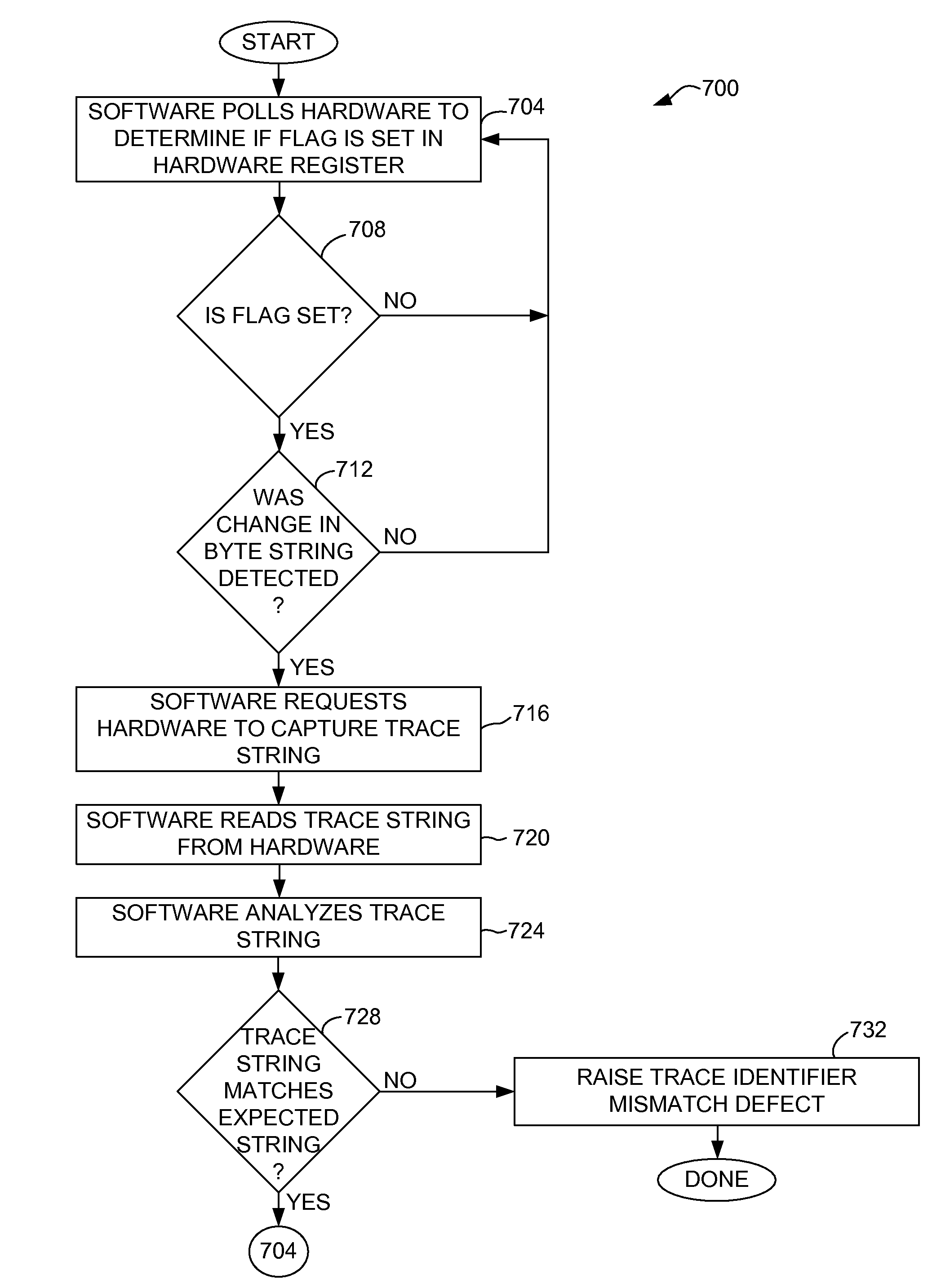
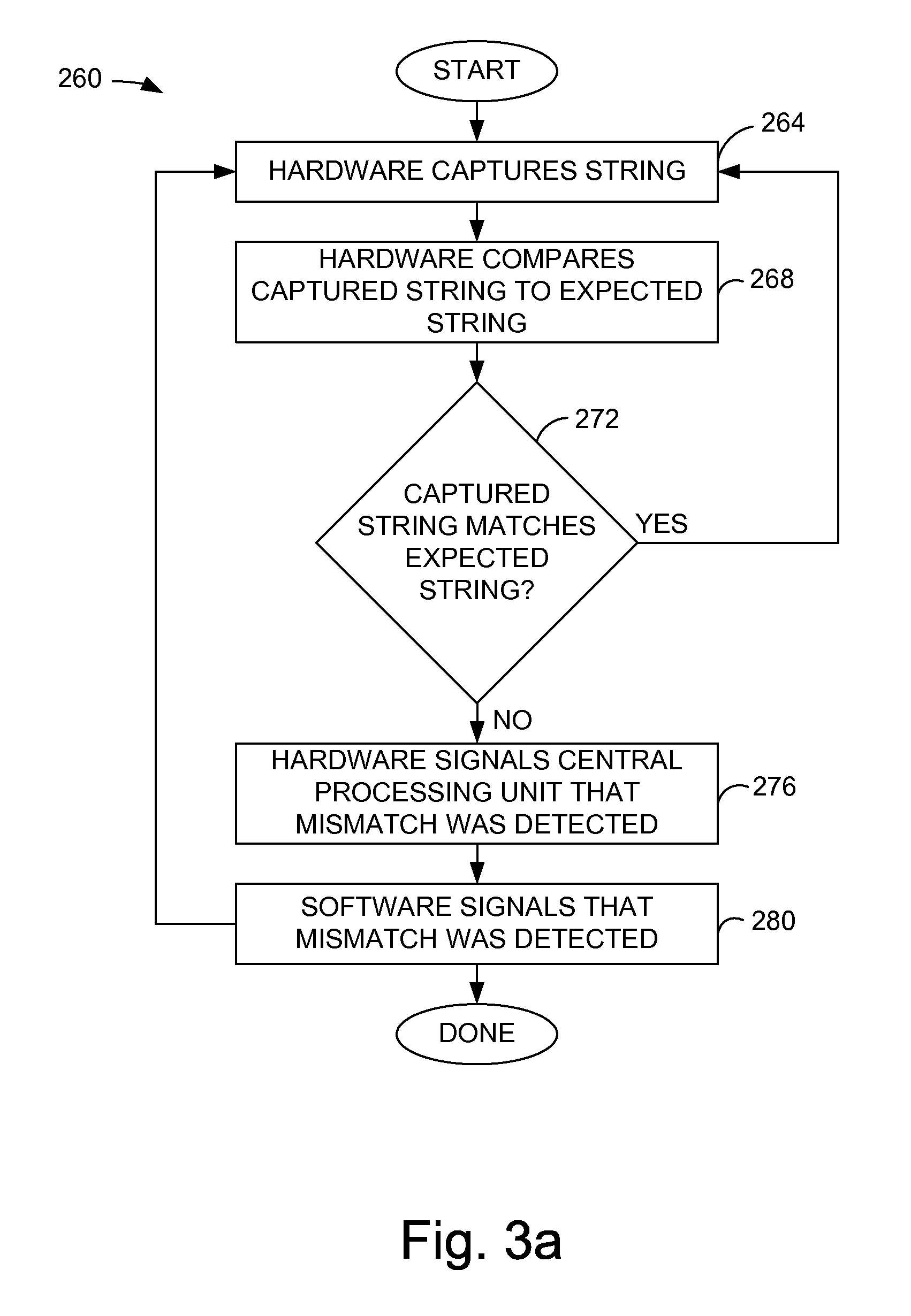
The present invention is about efficiently identifying trace identifier mismatches within a network. It involves detecting changes in trace information associated with a path using a detection system with a hardware component and a software component. The method allows for the detection of trace identifier mismatches along a path, which can be done efficiently and with minimal memory usage. The detection system can also monitor multiple circuits or paths simultaneously. The technical effects of the invention include improved efficiency and accuracy in identifying defects in network circuits.

Problems solved by technology

The demand for data communication services is growing at an explosive rate.
Monitoring trace identifier strings generally requires substantial resources and significant data processing.
As the number of circuits that are to be monitored increases, the hardware memory requirements needed in a trace identifier mismatch detection system increases.
When a relatively large number of circuits are to be monitored, it may not be possible to provide enough memory to support the monitoring of the relatively large number of circuits.
Hence, the time between when a trace mismatch arises and when the trace mismatch is detected may be relatively significant.
As a result, within a system in which specifications are such that a trace mismatch is effectively required to be detected within a certain amount of time, it may not be possible to support all the circuits and still meet minimum acceptable levels of system performance.

Method used


Image

  • Two-stage detection of trace identifier mismatches
  • Two-stage detection of trace identifier mismatches
  • Two-stage detection of trace identifier mismatches

Examples


Embodiment Construction

[0032]Monitoring trace strings such as J0, J1, and J2 path trace strings generally require a substantial amount of data processing. Monitoring a single trace string associated with a circuit or a path generally requires capturing a continuous string of bytes, determining a format of the string, determining the start of the string, and comparing the captured string with an expected string to identify a mismatch. In general, systems used to monitor trace strings have significant hardware requirements, and utilize a relatively significant amount of resources and time in order to detect a defect associated with a circuit. Further, when multiple formats are to be supported, e.g., formats such as both a synchronous digital hierarchy (SDH) format and a synchronous optical network (SONET) format, the hardware generally needs to be changed.

[0033]By using hardware to detect changes in trace information, and software to analyze substantially only those traces in which changes have been detecte...


PUM


Abstract

Methods and apparatus for processing a trace mismatch by using hardware to detect a change in a trace string and software to perform string analysis are disclosed. In accordance with one aspect of the present invention, a method for detecting a trace identifier mismatch using a detection system with a hardware component and a software component includes detecting a change in trace information associated with the path using the hardware component. The method also includes providing an indication of the change in trace information using the hardware component, obtaining the indication from the hardware component using the software component, and analyzing the trace information using the software component to determine if a trace identifier mismatch is present.

Description

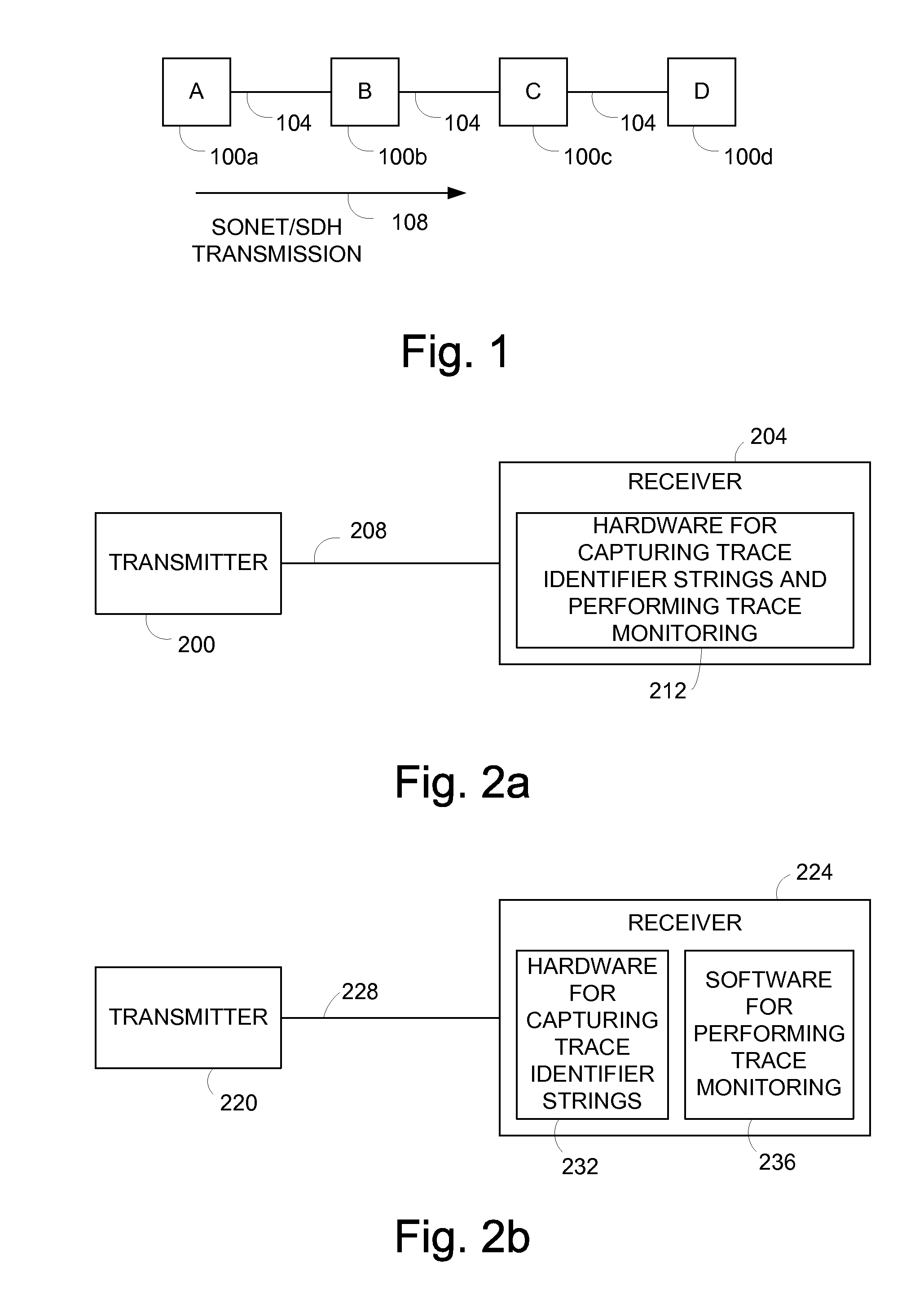
BACKGROUND OF THE INVENTION[0001]1. Field of Invention[0002]The present invention relates generally to network systems. More particularly, the present invention relates to efficiently detecting trace identifier mismatches using a system which includes hardware and software.[0003]2. Description of the Related Art[0004]The demand for data communication services is growing at an explosive rate. Much of the increased demand is due to the fact that more residential and business computer users are becoming connected to the Internet. To address the demand for data communication services, the use of optical networks, such as a synchronous digital hierarchy (SDH) network or a synchronous optical network (SONET), is becoming more prevalent. SONET and SDH networks are examples of time division multiplexed (TDM) networks. TDM networks generally allocate single lines to be used amongst multiple users, or customers of data communication services. The single lines may each be divided into slots of...

Claims


Application Information

Patent Timeline
Patent Type & Authority Patents(United States)
IPC IPC(8): G06F11/00
CPCH04J3/14H04J2203/006
Inventor BAILEY, DAVID
Owner CISCO TECH INC
Learn More