Cammed connector pin assembly and associated excavation apparatus

a technology of cammed connector pins and connector pins, which is applied in the direction of threaded fasteners, couplings, manufacturing tools, etc., can solve the problems of significant surface wear and loosening of wear members

Active Publication Date: 2009-10-20
HENSLEY INDUSTRIES INC
View PDF37 Cites 52 Cited by
  • Summary
  • Abstract
  • Description
  • Claims
  • Application Information

AI Technical Summary

Benefits of technology

[0009]With the wear member operatively telescoped onto the support member nose, first and second connector openings in opposite side wall portions of the wear member are generally aligned with a connector opening extending through the nose. The connector pin assembly is preferably of a “hammerless” construction which permits it to be placed in and removed from the aligned connector openings without pounding on the assembly with a sledge hammer or other driving implement. When the connector assembly is installed in these openings, opposite end portions of the assembly extend into the wear member connector openings and serve to block forward removal of the wear member from the support member.
[0010]According to a key aspect of the invention, the connector pin assembly is provided with tightening structure which is adjustable to rearwardly engage the wear member in both initial and rearwardly shifted tightened positions and prevent the wear member from shifting forwardly away from such positions along the support member nose. The tightening structure is representatively carried on a connector pin portion of the assembly and is movable between first and second positions to respectively engage the wear member in its initial and rearwardly shifted tightened positions to prevent forward shifting of the installed wear member from such tightened positions. The connector pin assembly is also provided with locking structure for releasably locking the wear member tightening structure in each of its first and second positions.
[0012]The connector pin portion of the assembly is illustratively formed from two coaxial, threadingly interconnected connector pin body portions having axially facing surfaces that may be threadingly moved toward and away from one another. The locking structure may include a resilient structure interposed between these facing surfaces and being compressible therebetween within the support member nose opening to lock the connector pin structure within the support member in a manner also preventing movement of the tightening member relative to the wear member.

Problems solved by technology

However, after the overall wear member / support member structure is used for a time the tremendous forces excavating forces that it is subjected to cause significant surface wear at the interior interface between the wear and support members.
This undesirably “loosens” the wear member and permits it to shift rearwardly along the support member to a rearwardly shifted tightened orientation.
During excavation operations this, in turn, permits the wear member to forwardly and rearwardly “rattle” on the support member in a manner undesirably accelerating abrasion wear at the support member / wear member surface interface.

Method used


Image

  • Cammed connector pin assembly and associated excavation apparatus
  • Cammed connector pin assembly and associated excavation apparatus
  • Cammed connector pin assembly and associated excavation apparatus

Examples


Embodiment Construction

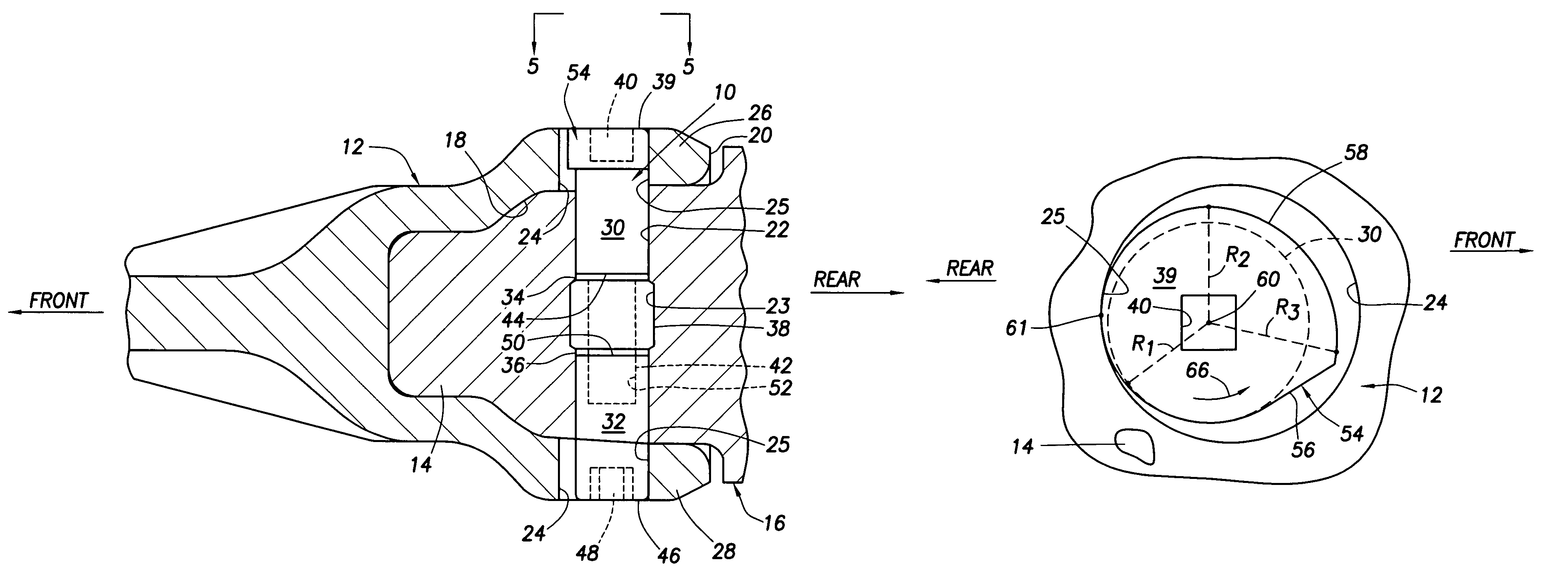
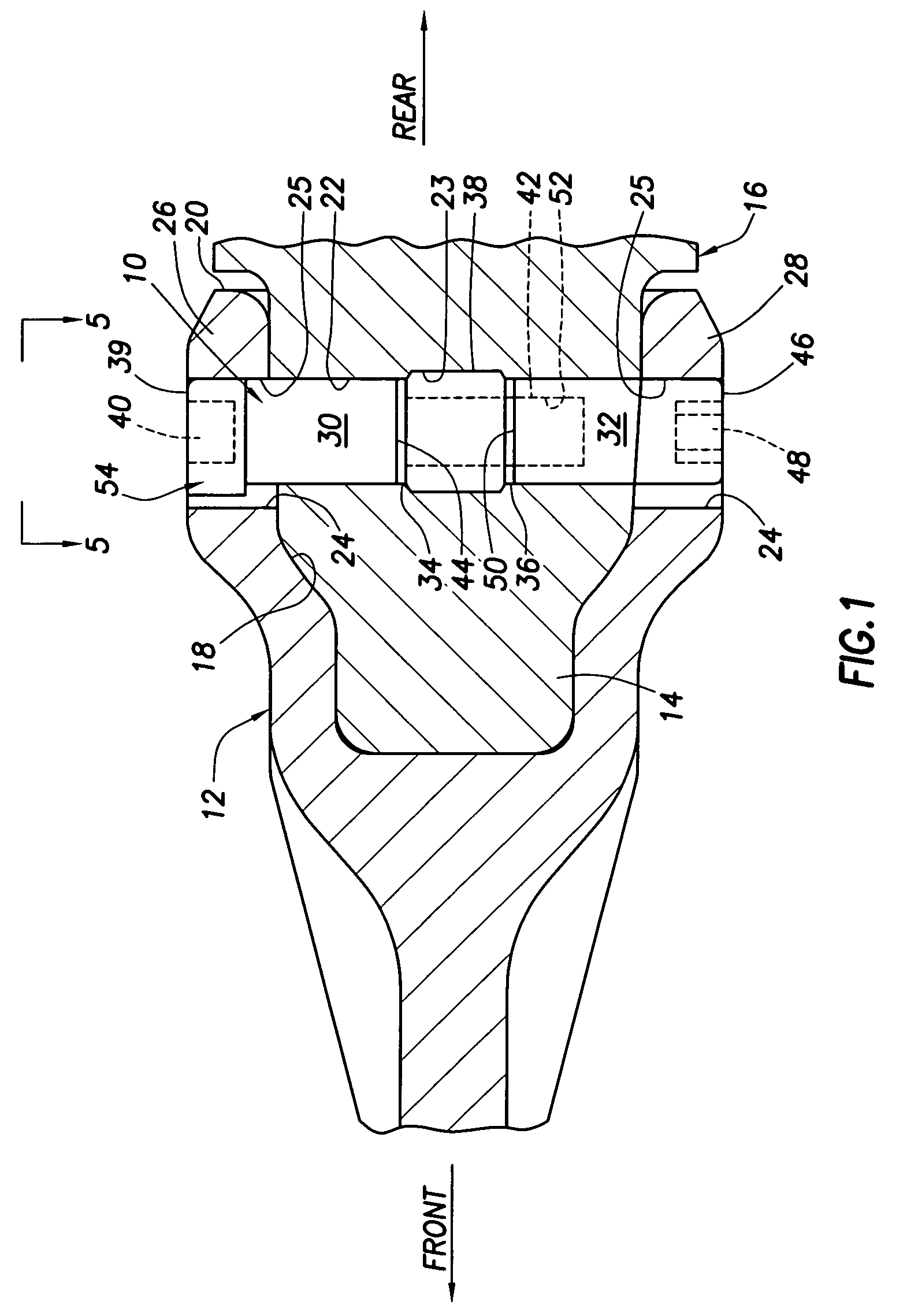
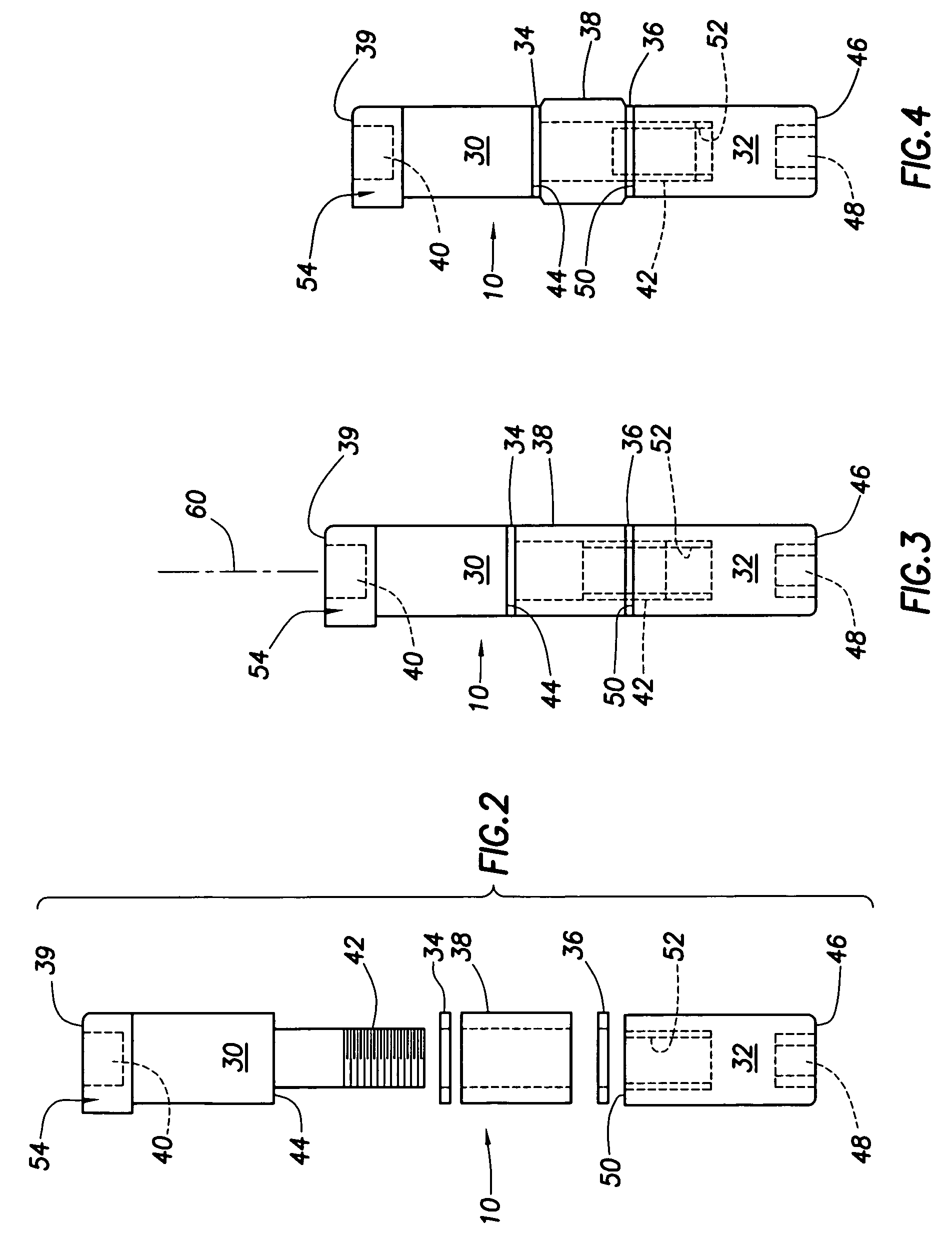
[0029]As illustrated in FIGS. 1-4, in a representatively illustrated embodiment thereof this invention provides a specially designed connector pin assembly 10 that is used to releasably hold a wear member, representatively an excavating tooth point 12, on the nose 14 of an associated support member, representatively an adapter structure 16. It will be appreciated by those of skill in this particular art that other types of wear members, such as for example an intermediate adapter, could also be captively and releasably retained on the adapter nose 14 by the connector pin assembly 10 if desired.

[0030]In a conventional manner, the replaceable tooth point 12 has an internal socket 18 extending in a forward direction inwardly from its rear end 20, with the tapered adapter nose 14 being complementarily received in the socket 18. A transverse, circularly cross-sectioned opening 22 extends through the adapter nose 14 and is generally aligned with corresponding openings 24 formed in opposit...


PUM


Abstract

A hammerless connector pin assembly is insertable in the aligned connector openings in telescoped excavation wear and support members and has associated locking structure for releasably locking the inserted assembly therein. The inserted assembly has opposite end portions that block removal of the wear member from the support member. One of such end portions has a laterally projecting cam member disposed thereon which is positioned within one of the wear member openings. As the interior surface of the wear member becomes worn from use and is able to shift further rearwardly along the support member, the cam member may be rotationally adjusted to maintain contact with the wear member to prevent forward movement thereof away from its rearward shifted position.

Description

BACKGROUND OF THE INVENTION[0001]The present invention generally relates to material displacement apparatus and, in a preferred embodiment thereof, more particularly relates to apparatus for releasably coupling a replaceable excavating tooth point or other wear member to an associated adapter nose structure.[0002]A variety of types of material displacement apparatus are provided with replaceable wear portions that are removably carried by larger base structures and come into abrasive, wearing contact with the material being displaced. For example, excavating tooth assemblies provided on digging equipment such as excavating buckets or the like typically comprise a relatively massive adapter portion which is suitably anchored to the forward bucket lip and has a reduced cross-section, forwardly projecting nose portion, and a replaceable tooth point having formed through a rear end thereof a pocket opening that releasably receives the adapter nose. To captively retain the point on the a...

Claims


Application Information

Patent Timeline
Patent Type & Authority Patents(United States)
IPC IPC(8): E02F9/28
CPCE02F9/2841Y10T403/1691
Inventor CAMPOMANES, PATRICK S.
Owner HENSLEY INDUSTRIES INC
Why Eureka
Try Eureka