Apparatus and method for wheelchair aerobic stationary exercise

a technology for stationary exercise and wheelchairs, applied in sport apparatuses, gymnastic exercise, therapy exercise, etc., can solve the problems of large footprint, inability to provide independent wheelchair wheel operation, and expense of devices

Inactive Publication Date: 2009-10-20
STANFORD CHRISTOPHER STEPHEN REECE
View PDF10 Cites 39 Cited by
  • Summary
  • Abstract
  • Description
  • Claims
  • Application Information

AI Technical Summary

Benefits of technology

[0020]One aspect of the invention is a simple mechanism to engage the rear wheels of the wheelchair with a resistance means so that the occupant can exercise from a set position. One benefit of a lift mechanism is that the device can be provided with a much smaller footprint and weight as compared to prior art ramp devices where the wheelchair is driven up a ramp to access the resistance means.
[0032]In some embodiments, physiological measurements may be combined with the speed measurements and force calculations, and the device can serve as a simple physiological study device.

Problems solved by technology

Disadvantages of the prior art device include its large footprint, the expense of the device, and the inability to provide independent wheelchair wheel operation.
Another disadvantage of prior art devices is that they are typically designed for a forward direction only, so that the devices work when the wheelchair wheels are driven in a forward direction, but may not work well when the wheelchair wheels are driven in a reverse direction.
Although these forward devices may improve torso and arm strength, they do not provide a balanced exercise regimen to strengthen the back muscles and to lengthen the torso muscles.
If the predominant movements are in a forward direction, the back muscles may not be appropriately strengthened, and the torso muscles will have a tendency to constrict.
While this device is useful for clinical studies, it is large and expensive.

Method used


Image

  • Apparatus and method for wheelchair aerobic stationary exercise
  • Apparatus and method for wheelchair aerobic stationary exercise
  • Apparatus and method for wheelchair aerobic stationary exercise

Examples


example

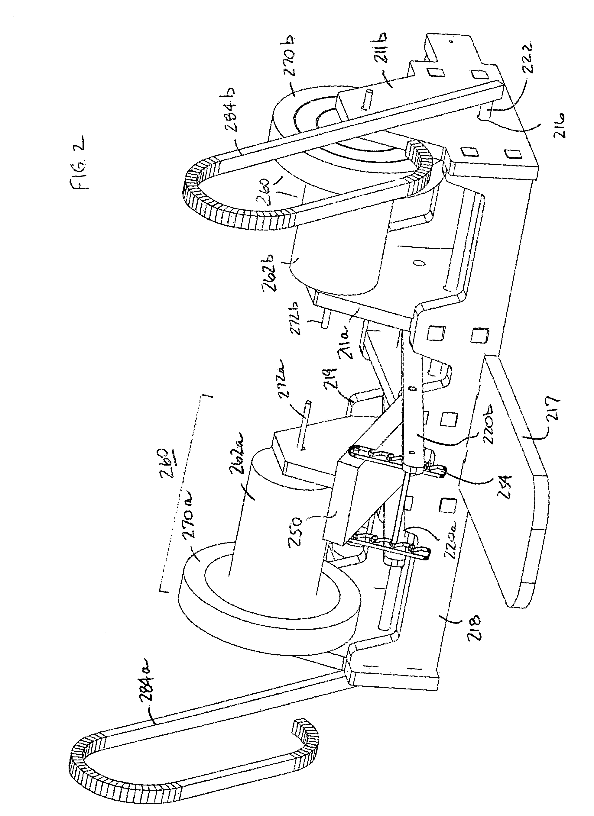
[0080]Olympic weights have a thin circular disk with the bulk of the cast iron mass as a widened perimeter ring, as would be a design option for optimized flywheels. In this example, two 35 Olympic weights could be used in lieu of two 501b weights of the same diameter, as their rotational inertias are equivalent.

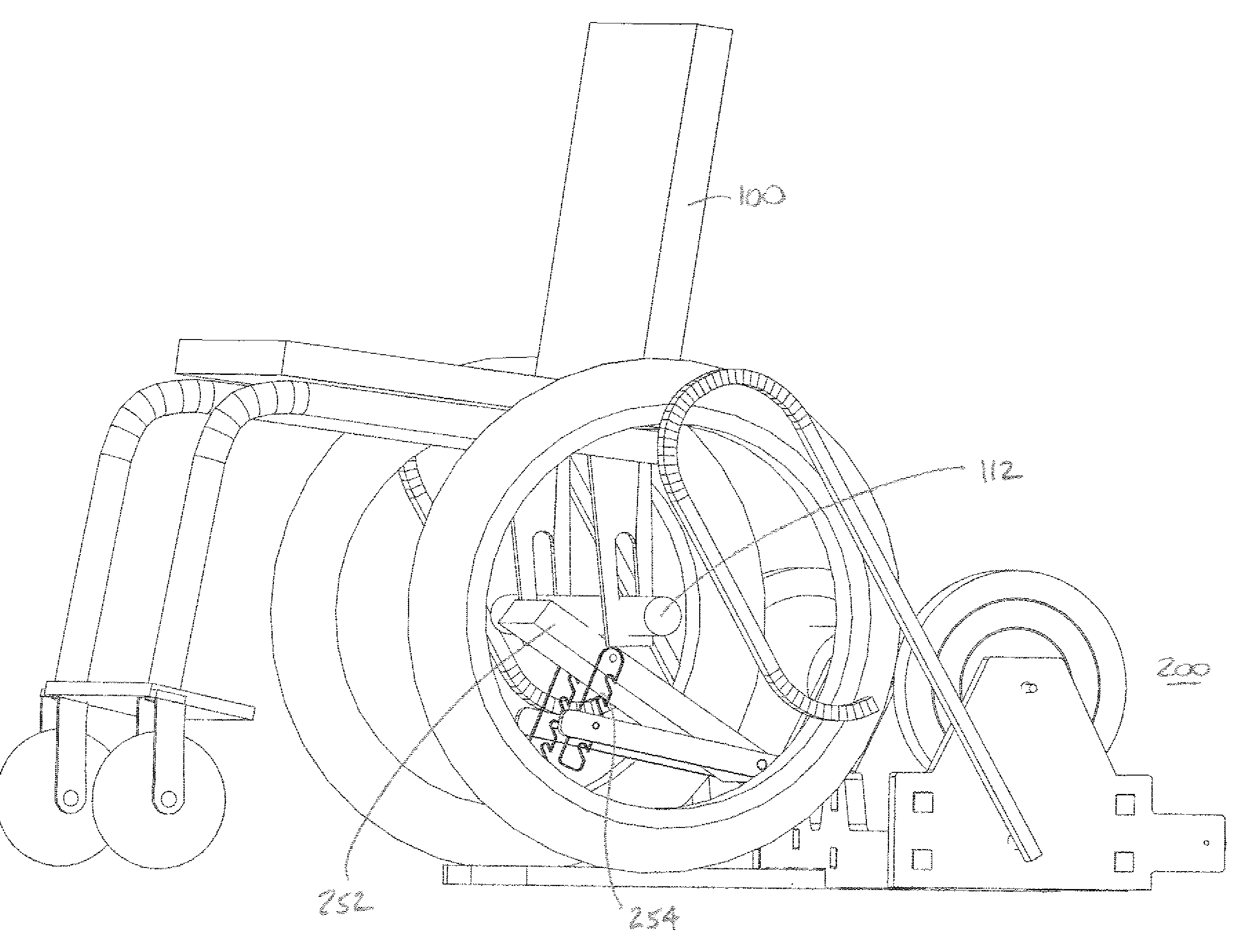
[0081]A typical total flywheel inertial mass is provided to approximate 200 pounds of translational mass. This mass accommodates the average wheelchair user and wheelchair weight. The device uses a concept of equivalent inertia, but is also able to provide that equivalent inertia with a relatively low flywheel mass because of the inertial characteristics of the flywheels. For example, the 200 pounds of translational mass can typically be approximated with total flywheel mass of 70 to 100 pounds, depending upon the diameter and shape of the flywheels and the diameter of the wheel engagement means (contact wheel) which determine the rotational speed of the connected flywheels ...


PUM


Abstract

An improved wheelchair trainer with independent flywheel resistance for each wheelchair rear wheel. A lever-operated cam raises the wheelchair rear axle by pushing an inclined block against the axle and forces the rear wheels against wheel engagement means. As one or both rear wheels are turned, each wheel engagement means turns a flywheel in proportion to the speed of the wheel. Force and work may be calculated from the measured rotational speed of the flywheels. A hand-cycle attachment may drive the flywheel resistance.

Description

RELATED APPLICATIONS[0001]This application is related to U.S. Provisional Patent Application No. 60 / 761,186 filed Jan. 23, 2006, and claims the filing date of that application.BACKGROUND[0002]1. Field of Invention[0003]This invention relates to a wheelchair exercise trainer.[0004]2. Prior Art[0005]A typical prior art trainer provides a pair of elongated rollers set in a frame. A ramp is typically provided so that the chair may be guided up the ramp to a platform with the recessed rollers. FIG. 1 is a perspective view of a typical prior art trainer.[0006]Disadvantages of the prior art device include its large footprint, the expense of the device, and the inability to provide independent wheelchair wheel operation.[0007]Another disadvantage of prior art devices is that they are typically designed for a forward direction only, so that the devices work when the wheelchair wheels are driven in a forward direction, but may not work well when the wheelchair wheels are driven in a reverse d...

Claims


Application Information

Patent Timeline
Patent Type & Authority Patents(United States)
IPC IPC(8): A63B22/00A63B69/16A63B71/00
CPCA63B21/225A63B22/0002A63B23/12A63B71/0009A63B21/005A63B2225/093A63B69/16A63B2022/0041A63B2069/164A63B2069/165A63B2069/168A63B2071/0018A63B2071/027A63B2220/30A63B2220/54A63B21/0081A63B21/008Y10S482/904A63B23/1209A63B23/03541A63B23/1263A63B21/4049
Inventor STANFORD, CHRISTOPHER STEPHEN REECE
Owner STANFORD CHRISTOPHER STEPHEN REECE
Why Eureka
Try Eureka