
High-definition vertical-scan interferometry

a vertical-scan interferometry and high-definition technology, applied in the direction of instruments, measurement devices, using optical means, etc., can solve the problems of vsi errors being completely removed from the vsi, phase calculation does not utilize the conventional n-frame phase shifting approach of prior, and is not possible with prior-art approaches

Active Publication Date: 2009-10-20
BRUKER NANO INC
View PDF15 Cites 18 Cited by
  • Summary
  • Abstract
  • Description
  • Claims
  • Application Information

AI Technical Summary

Benefits of technology

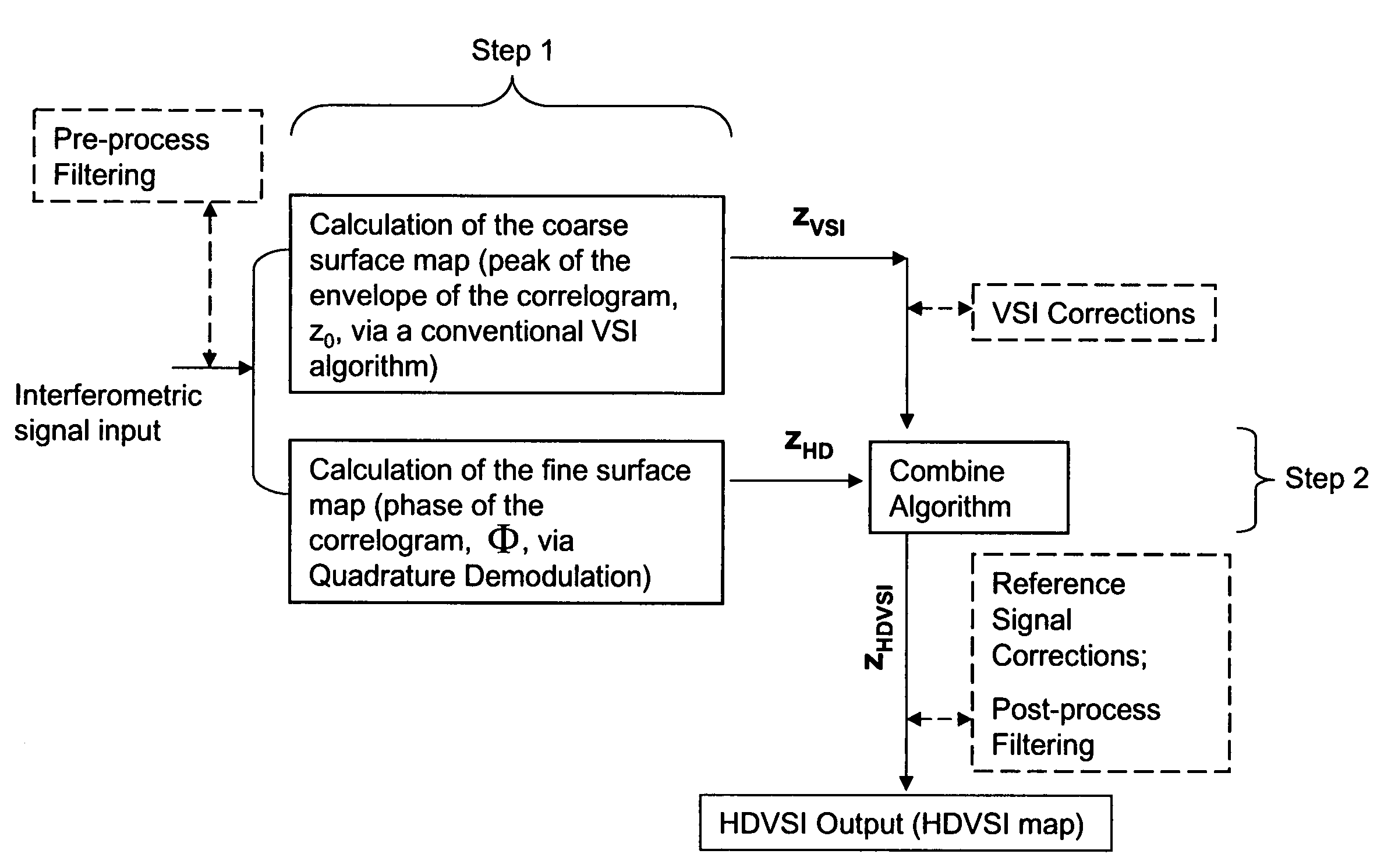
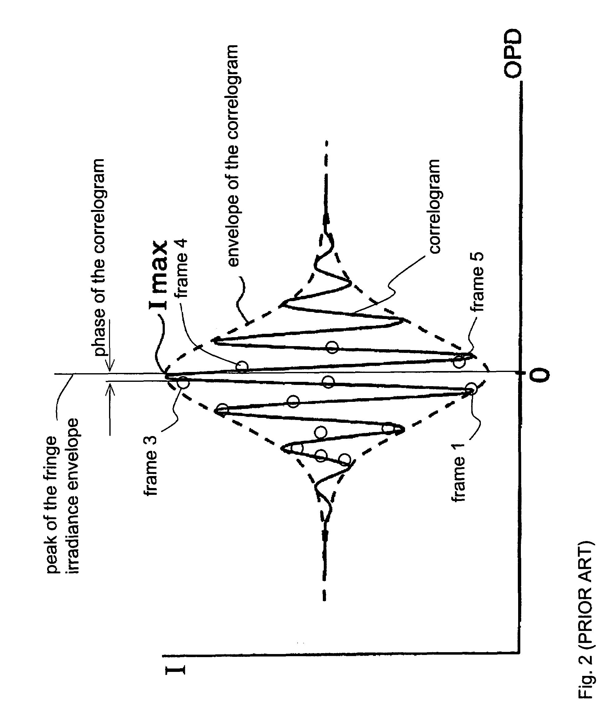
[0011]The HDVSI method of the invention is carried out by performing the coarse calculation of surface profile with a conventional VSI method such as center of mass (COM), quadrature center of mass (QCOM), or zero crossing detection (ZCD). According to a primary aspect of the invention, the phase calculation is carried out concurrently using the same VSI frame data set. However, the phase calculation does not utilize the conventional n-frame phase shifting approach of the prior art. Instead, it utilizes a quadrature-demodulation (QD) algorithm applied to the irradiance data contained in the VSI correlogram. As a result, the phase calculation is independent of the position of any particular interferometric fringe and, therefore, it is more accurate and its results are more certain than those produced by the combined VSI / PSI methods of the prior art. Once both calculations are accomplished, the phase data are incorporated into the coarse profile data through a unique “unwrapping” method that yields a final surface map with sub-nanometer resolution within a large z-height range.

Problems solved by technology

However, the phase calculation does not utilize the conventional n-frame phase shifting approach of the prior art.
As a result, the VSI errors are completely removed from the VSI coarse map through the rounding process, which is not possible with prior-art approaches.

Method used


Image

  • High-definition vertical-scan interferometry
  • High-definition vertical-scan interferometry
  • High-definition vertical-scan interferometry

Examples


Embodiment Construction

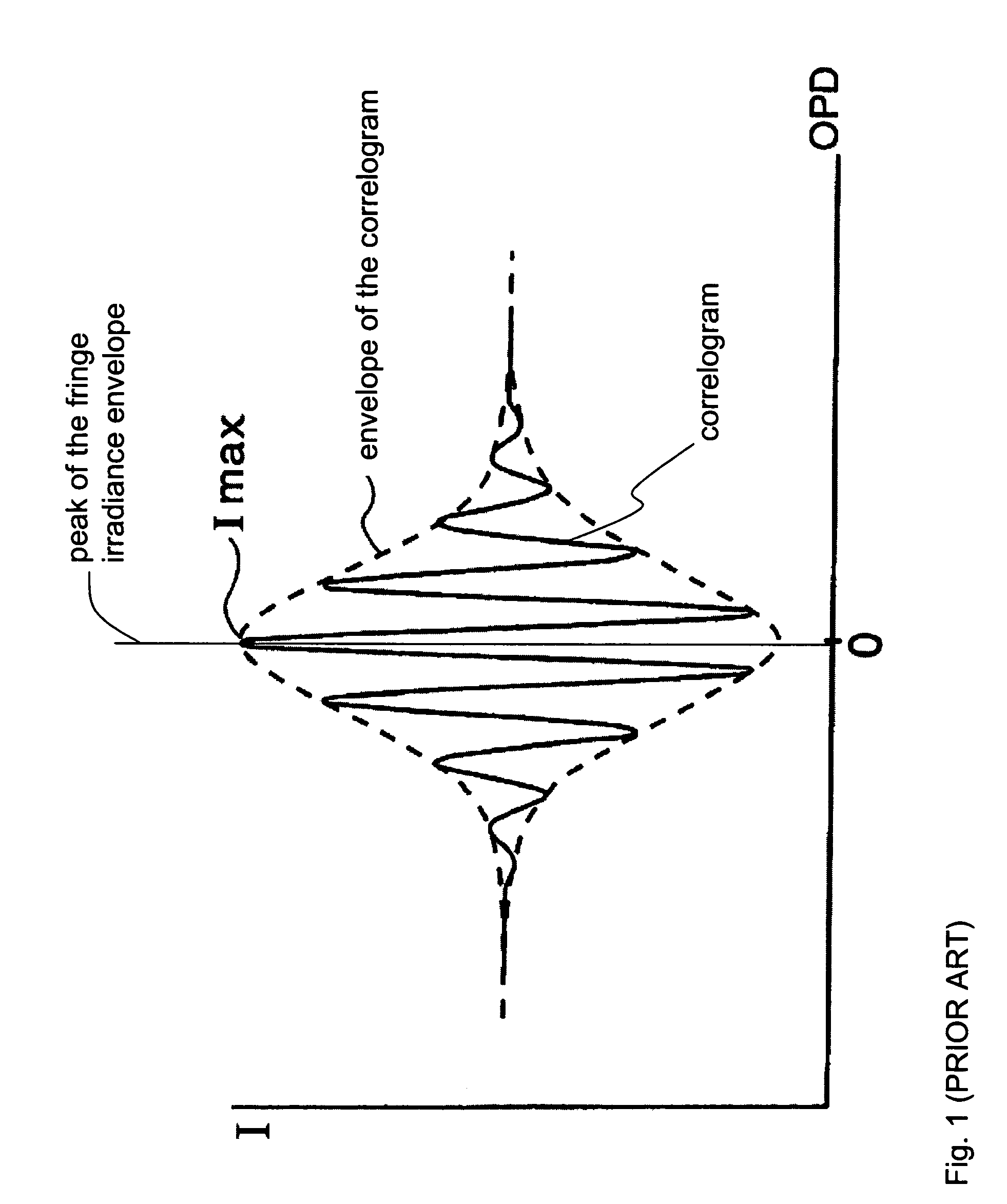
[0030]The idea of the invention is to map a sample surface by determining simultaneously from a single VSI scan two independent parameters—the peak position of the fringe envelope and the phase of the correlogram, where the determination of the latter does not involve the use of a phase-shifting algorithm that requires the prior acquisition of all scan data. To that end, the correlograms produced at the light detector during a conventional VSI scan are processed in two different ways. On one hand, a conventional method is applied to the correlogram to calculate the peak of its envelope (at each pixel) to determine a coarse surface-height value. For example, a center-of-mass method (COM), or a quadrature COM, or a zero-crossing detection method (ZDE) may be used for this purpose. Mapping the surface with such a conventional method is known to produce a vertical resolution of approximately 3 nm rms on a smooth reflective sample. On the other hand, to refine the VSI surface map to a su...


PUM


Abstract

A broadband interferometric vertical scan of a sample surface is performed to produce interference data in conventional manner. A coarse surface profile of the surface is obtained in real time using a conventional technique, such as a center-of-mass calculation. A fine surface map is obtained concurrently using a quadrature-demodulation algorithm applied in real time to the same interference data used for the coarse surface calculation. The fine surface map is then combined with the coarse surface profile using an unwrapping technique that produces a final surface map with sub-nanometer resolution within a large height range.

Description

BACKGROUND OF THE INVENTION[0001]1. Field of the Invention[0002]This invention relates in general to vertical-scanning interferometric (VSI) techniques for surface characterization. In particular, it relates to a new method for combining information about the peak of the envelope and the phase of a VSI correlogram.[0003]2. Description of the Related Art[0004]Optical surface profilometry enables the performance of non-contact measurements of fragile surfaces with high resolution and at high measurement speeds. Several widely accepted techniques are available for calculating surface topography from optical interference data.[0005]Phase-shifting interferometry (PSI), for example, is based on changing the phase difference between two coherent interfering beams at a single wavelength, λ, in some known manner, for example by changing the optical path difference (OPD) either continuously or discretely with time. Several measurements of light intensity with different OPD values, usually equ...

Claims


Application Information

Patent Timeline
Patent Type & Authority Patents(United States)
IPC IPC(8): G01B11/02
CPCG01B11/2441G01B9/02079G01B9/02083G01B9/0209G01B9/02057
Inventor CHEN, DONG
Owner BRUKER NANO INC
Learn More