
Terahertz frequency band aperture coding high-resolution middle and long distance staring imaging device and method

A staring imaging, terahertz technology, applied in measurement devices, radio wave reflection/re-radiation, utilization of re-radiation, etc., can solve the difficulty of quasi-optical design of imaging systems, limited imaging distance, and difficult non-mechanical uniform scanning of imaging planes. implementation issues

Active Publication Date: 2017-05-31
NAT UNIV OF DEFENSE TECH
View PDF4 Cites 17 Cited by
  • Summary
  • Abstract
  • Description
  • Claims
  • Application Information

AI Technical Summary

Problems solved by technology

Although the terahertz aperture coded high-resolution imaging radar technology has many advantages over the traditional radar imaging technology, there are still some problems that need to be solved urgently, such as the limited imaging distance of the system, and the non-mechanical uniform scanning of the imaging plane by the terahertz beam is difficult to achieve. The quasi-optical design of the imaging system is more difficult

Method used


Image

  • Terahertz frequency band aperture coding high-resolution middle and long distance staring imaging device and method
  • Terahertz frequency band aperture coding high-resolution middle and long distance staring imaging device and method
  • Terahertz frequency band aperture coding high-resolution middle and long distance staring imaging device and method

Examples


Embodiment Construction

[0050] The present invention will be further described below in conjunction with the accompanying drawings and specific embodiments.

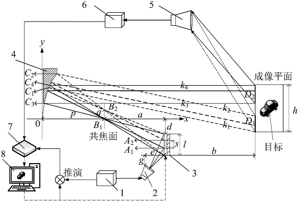
[0051] In the present invention, considering that the working modes of the device in the horizontal and vertical directions are symmetrical, the present invention will be described by taking the vertical direction as an example. established as figure 1 In the Cartesian coordinate system shown in , the origin of the coordinates coincides with the apex of the parabolic primary reflector, the positive direction of the horizontal axis x is to the right, and the positive direction of the vertical axis y is vertically upward. The present invention proposes a terahertz frequency band aperture coding high-resolution mid-to-long distance staring imaging device, as shown in the attached figure 1 As shown, the device includes a terahertz transmitting module 1 , a transmitting antenna 2 , an electronically controlled sub-reflector array 3 , a parabolic pr...


PUM


Abstract

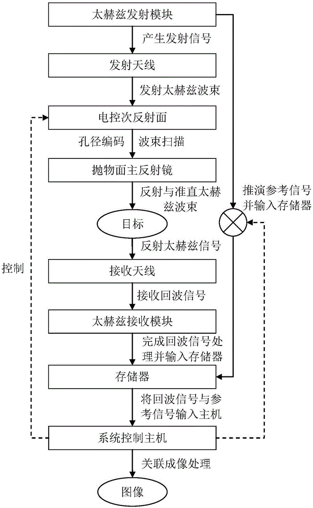
The present invention belongs to the radar imaging technology field, and especially relates to a terahertz frequency band aperture coding high-resolution middle and long distance staring imaging device and method. The imaging device comprises a terahertz transmission module 1, a transmission antenna 2, an electric control secondary reflector array 3, a paraboloid primary mirror 4, a receiving antenna 5, a terahertz receiving module 6, a memory 7 and a system control host 8. The terahertz transmission module is connected with the transmission antenna, and the electric control secondary reflector array is connected with a system control host; the paraboloid primary mirror is configured to perform reflection and alignment of the terahertz coding wave beam; the receiving antenna collects the scattering echo signals of the surface of a target; the terahertz receiving module is configured to perform low noise amplification, frequency mixing and quadrature demodulation processing of the scattering echo signals; and the system control host performs relation imaging processing of the echo signals and the reference signals to obtain a target reconstruction image. The terahertz frequency band aperture coding high-resolution middle and long distance staring imaging device and method obtain the high-resolution capability in the wave beam of the identical caliber traditional radar diffraction limit and are fast in mode switching.

Description

technical field [0001] The invention belongs to the technical field of radar imaging, and in particular relates to a high-resolution radar staring imaging technology, in particular to a terahertz frequency band aperture coding high-resolution mid-to-long distance staring imaging device and method. Background technique [0002] High-resolution radar imaging is an important means to realize battlefield reconnaissance, target detection and identification, and plays a pivotal role in ensuring national strategic security and competing for battlefield initiative. Conventional microwave radar systems can actively detect, have strong penetrating capabilities, and can work all day and all day long. Frame rate, high resolution front view imaging. Although Synthetic Aperture Radar (SAR) and Inverse Synthetic Aperture Radar (ISAR) imaging can obtain high resolution in the lateral direction through synthetic aperture, both rely on the relative motion between the radar and the target, an...

Claims


Application Information

Patent Timeline
IPC IPC(8): G01S13/89
CPCG01S13/89
Inventor 罗成高秦玉亮邓彬王宏强陈硕
Owner NAT UNIV OF DEFENSE TECH
Learn More