Negative feedback amplifier for transmitter, transmitter, and method of correcting error in the negative feedback amplifier
a negative feedback amplifier and negative feedback technology, applied in the field of negative feedback amplifiers, can solve problems such as the deformation of ellipse, the deformation of transmission performance, and the deformation of sensitivity of a receiver, so as to achieve the effect of improving the magnitude of error vectors
- Summary
- Abstract
- Description
- Claims
- Application Information
AI Technical Summary
Benefits of technology
Problems solved by technology
Method used
Image
Examples
first embodiment
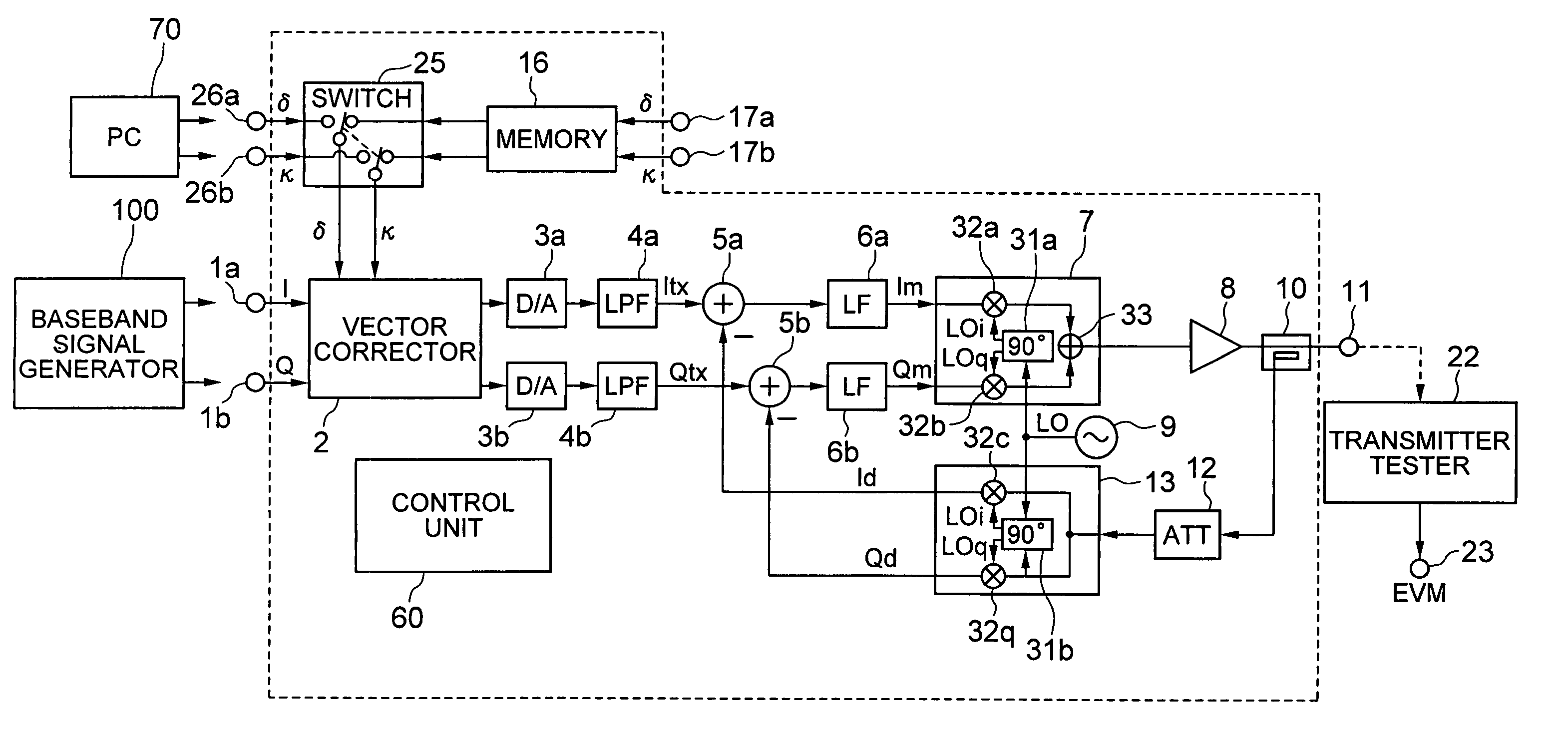
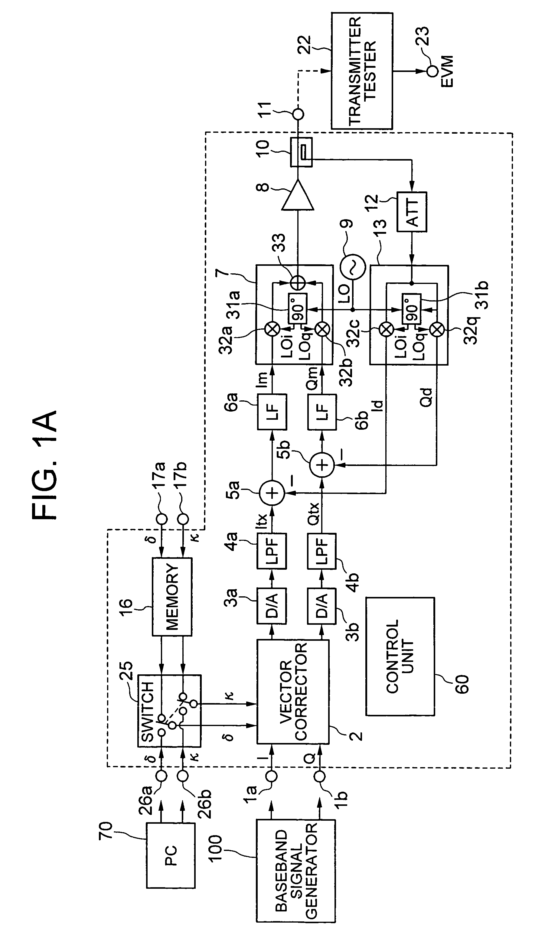
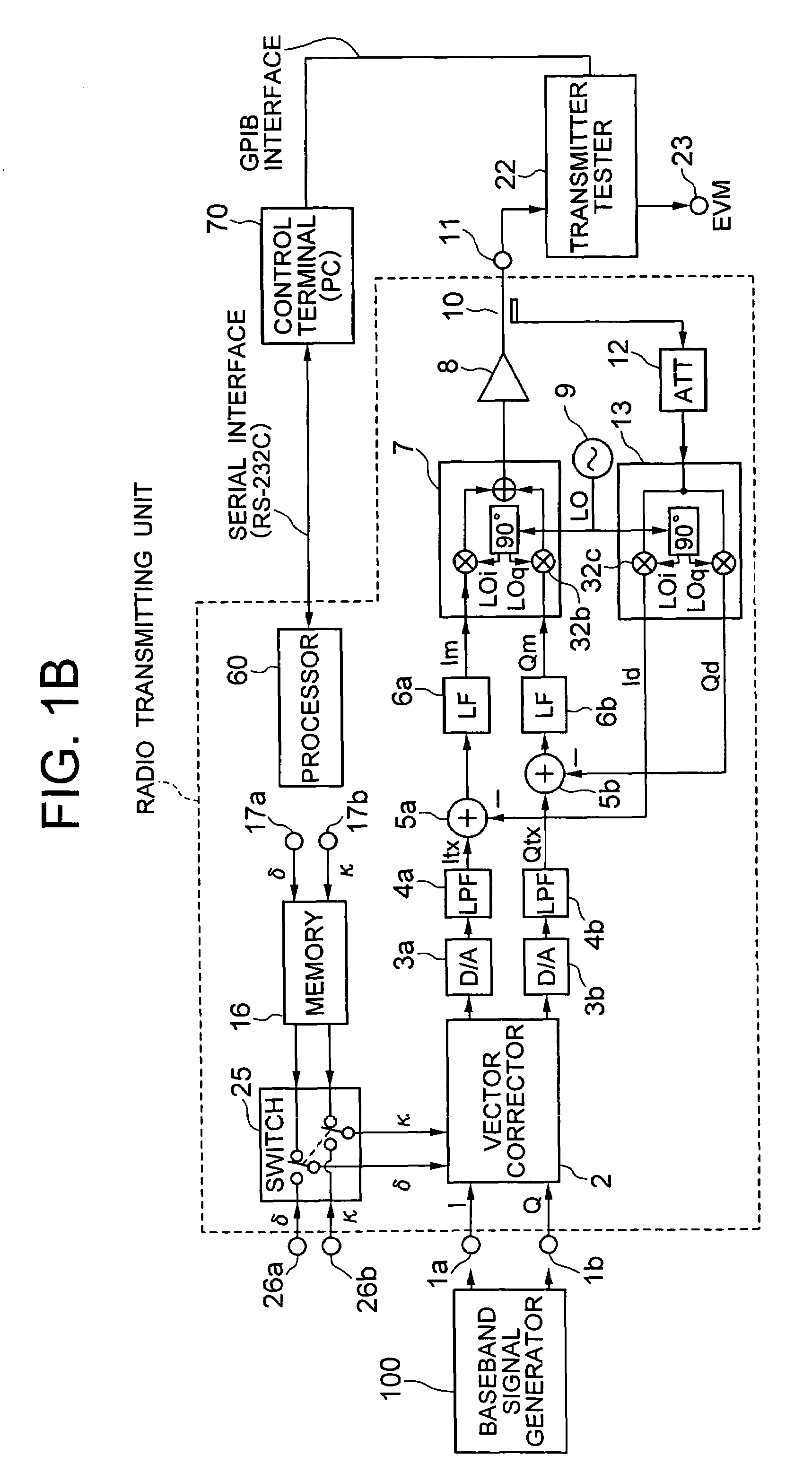
[0036]the present invention will be described with reference to FIGS. 1 and 2. FIG. 1 is a block diagram showing a transmitter to which the present invention is applied. The portion enclosed in a dotted line of FIG. 1 indicates a transmitting unit including a Cartesian loop negative feedback amplifier for performing an error correcting process according to the present invention. In this embodiment, a general-purpose quadrature demodulator 13 (for example, a commercially available demodulator IC) is used, and the method of correction in the demodulator 13 is disclosed.
[0037]The I signal and the Q signal of the baseband signal containing voice data or the other information are generated in a baseband signal generator 100. The digital input baseband I signal and the digital input baseband Q signal are inputted at input terminals 1a and 1b of a vector corrector 2. The vector corrector 2 performs a vector correcting process with respect to these digital signals. Concretely, the vector co...
second embodiment
[0057]In turn, the invention arranged to detect the phase error and the amplitude error with an error detector will be described with reference to FIGS. 3 and 4. FIG. 3 shows a transmitter having a Cartesian loop negative feedback amplifier to be used for executing the correcting method of the quadrature demodulator with no transmitter tester. The arrangement and the operation of the essential portion of the transmitter are likewise to those shown in FIGS. 1A and 1B. In this embodiment, however, an error detector 30 is newly provided. The error detector 30 includes a phase difference detector 14 and an amplitude difference detector 15.
[0058]In FIG. 3, for detecting and adjusting the errors (d, k) of the quadrature demodulator 13 in a factory or before shipment of the product, a terminator 31 is connected with an output terminal 11 through a switch 32. In succession, the testing I and Q signals are inputted into the input terminals 1a and 1b, respectively. Further, the I and Q signal...
third embodiment
[0079]The operation of the third embodiment will be described with an example of a transmission frame as shown in FIG. 8. The transmission frame 50 shown by (a) in FIG. 8 is composed of a linearizer preamble portion (LP), a preamble portion (P), a synchronous signal portion (SW), and a data portion. The linearizer preamble portion is a training timing interval placed at the head of the frame for the purpose of various trainings of the transmitter. The actual transmission signal in the transmission frame 50 is a portion of a modulated signal after the linearizer preamble portion (see (b) of FIG. 8). The preamble portion and the synchronous signal portion are the known fixed patterns to be transmitted for taking a timing synchronization with a receiver. The waveforms of the transmission frame (a) and the baseband signal (b) are generated according the timing signals (c) and (d) sent from the control unit 61. The transmission frame is built with the fall of the frame signal (c) shown i...
PUM
 Abstract
Description
Claims
Application Information
 - R&D
- Intellectual Property
- Life Sciences
- Materials
- Tech Scout
- Unparalleled Data Quality
- Higher Quality Content
- 60% Fewer Hallucinations
Browse by: Latest US Patents, China's latest patents, Technical Efficacy Thesaurus, Application Domain, Technology Topic, Popular Technical Reports.
© 2025 PatSnap. All rights reserved.Legal|Privacy policy|Modern Slavery Act Transparency Statement|Sitemap|About US| Contact US: help@patsnap.com


