Supercharge Your Innovation With Domain-Expert AI Agents!

Object oriented finite element modeling tools

a finite element modeling and object-oriented technology, applied in the field of conducting finite element modeling, can solve the problems of rendering useless, requiring an excessive amount of time for creating an appropriate finite element,

Inactive Publication Date: 2009-10-20
THE BOEING CO
View PDF6 Cites 0 Cited by
  • Summary
  • Abstract
  • Description
  • Claims
  • Application Information

AI Technical Summary

Benefits of technology

The invention is a method and apparatus for creating a finite element model of a structure using a mesh of nodes and nodal- pointers. The method involves superimposing a mesh onto a wire-frame geometry and creating a set of geometric elements using the rectangular mesh. The apparatus includes an array-forming means for forming the mesh and a modeling-means for creating the finite-element model. The invention also includes a storage medium containing instructions for creating finite element models. The technical effects of the invention include improved accuracy and efficiency in analyzing and designing structures using finite element models.

Problems solved by technology

For instance, a designer using known FEM tools generally requires an excessive amount of time to create an appropriate FEM for even a relatively simple structure.
Further, once such a FEM is created, it may be rendered useless should the designer wish to make anything but the most modest changes to the structure's design.

Method used


Image

  • Object oriented finite element modeling tools
  • Object oriented finite element modeling tools
  • Object oriented finite element modeling tools

Examples


Embodiment Construction

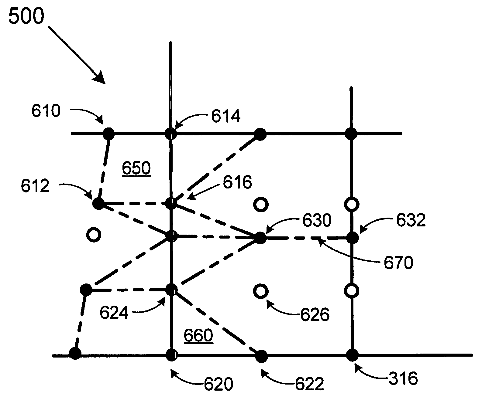
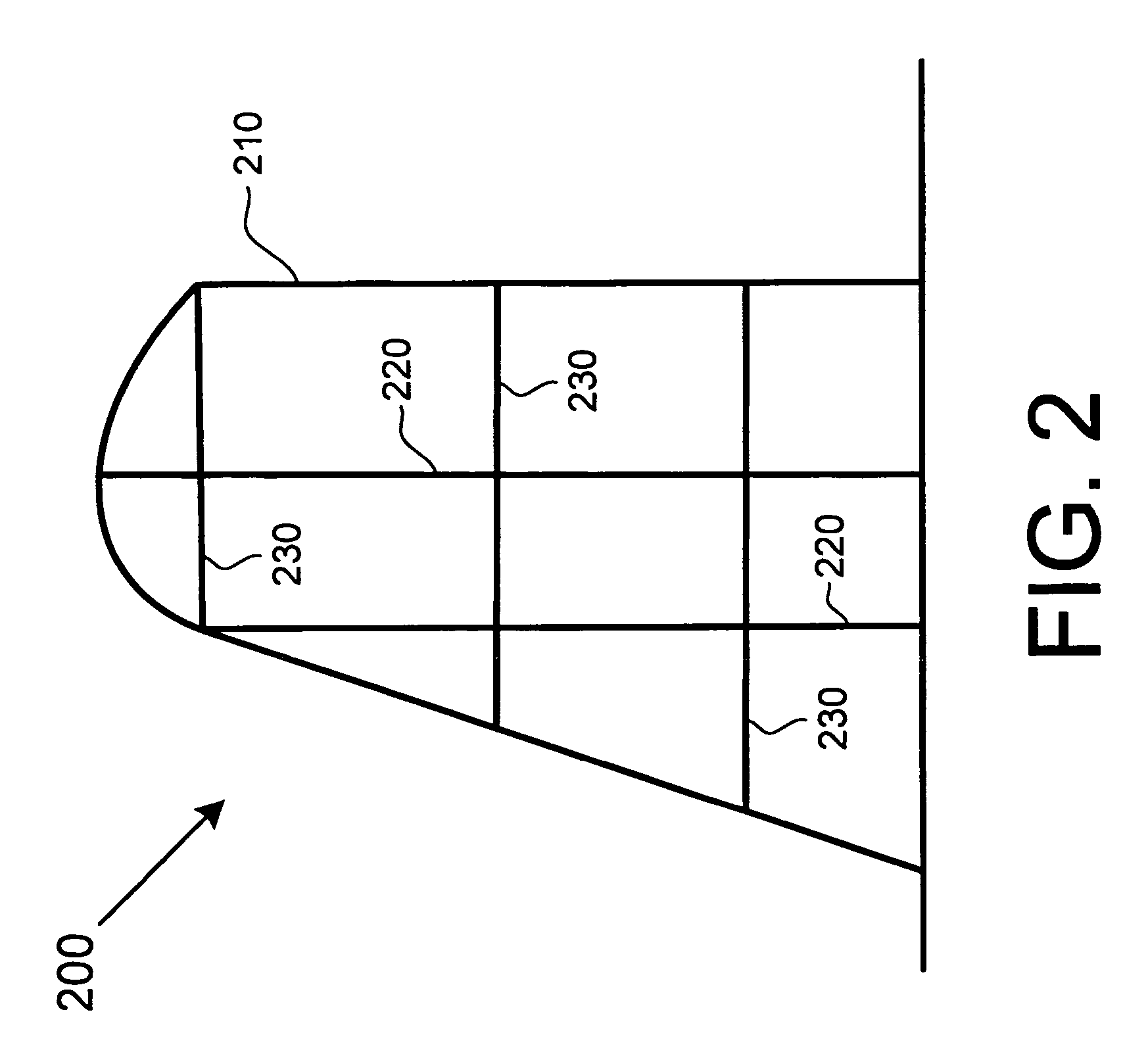
[0022]The advantages of using the disclosed methods and systems are notable not just for their apparent utility, but also because they transcend any comparable approach relating to finite element model formation. The inventor of the disclosed methods and systems has created an entirely new approach to FEM tools with new and unique advantages. Such advantages include, but are not limited to, the availability of tools capable of quickly developing new FEMs despite dramatic design changes that might be made to a given structure. Such advantages also include improved data structures, e.g., rectangular arrays, that lend themselves to the availability of object-oriented FEM software that is both highly portable and capable of treating FEMs as objects. For example, while analyzing a non-rectangular object, such as a triangular wing, the actual number of FEM nodes might decrease toward the tip of the wing. However, the node topology pathways of the wing (a pathway capable of being represent...


PUM


Abstract

Techniques for creating a finite element model are disclosed that include various processes including: superimposing a rectangular array of nodes and nodal-pointers onto a wire-frame geometry, and creating a set of geometric-elements using the rectangular array.

Description

FIELD OF THE INVENTION[0001]This invention relates to methods and systems for conducting finite element modeling.BACKGROUND OF THE INVENTION[0002]The Finite Element Model (FEM) is a tool useful for determining the integrity of a given mechanical structure. For example, aircraft designers have long used finite element models to predict how internal and external stresses will manifest themselves throughout each portion of a particular wing design during various flight maneuvers.[0003]While FEMs play an important part in the design and testing of aircraft, automobiles, buildings and hundreds of other structures, the computer-based tools available performing finite state analysis have a long history of unresolved shortcomings. For instance, a designer using known FEM tools generally requires an excessive amount of time to create an appropriate FEM for even a relatively simple structure. Further, once such a FEM is created, it may be rendered useless should the designer wish to make anyt...

Claims


Application Information

Patent Timeline
Patent Type & Authority Patents(United States)
IPC IPC(8): G06F17/50G06F17/10G06F7/60G06G7/48
CPCG06T17/20
Inventor THUNEMANN, PAUL Z.
Owner THE BOEING CO
Features
  • R&D
  • Intellectual Property
  • Life Sciences
  • Materials
  • Tech Scout
  • Unparalleled Data Quality
  • Higher Quality Content
  • 60% Fewer Hallucinations
Learn More