
Disk array device and failure response verification method thereof

a technology of failure response and array device, which is applied in the direction of error detection/correction, instruments, computing, etc., can solve the problem that verification cannot be conducted in the actual environment of the storage system

Inactive Publication Date: 2009-10-27
GOOGLE LLC
View PDF8 Cites 106 Cited by
  • Summary
  • Abstract
  • Description
  • Claims
  • Application Information

AI Technical Summary

Benefits of technology

Facilitates easy verification of server device settings for failure responses within the actual network environment without additional software installations, streamlining the testing process and preventing data damage through backup and restoration processes.

Problems solved by technology

Further, with the input / output test system described above, since troublesome procedures of having to install a test program in each information processing device will become required, and since testing is conducted with the simulated storage apparatus, there is a problem in that the verification cannot be conducted in the actual environment of the storage system.

Method used


Image

  • Disk array device and failure response verification method thereof
  • Disk array device and failure response verification method thereof
  • Disk array device and failure response verification method thereof

Examples


Embodiment Construction

[0029]An embodiment of the present invention is now explained in detail with reference to the drawings.

(1) Configuration of Storage System According to Present Embodiment

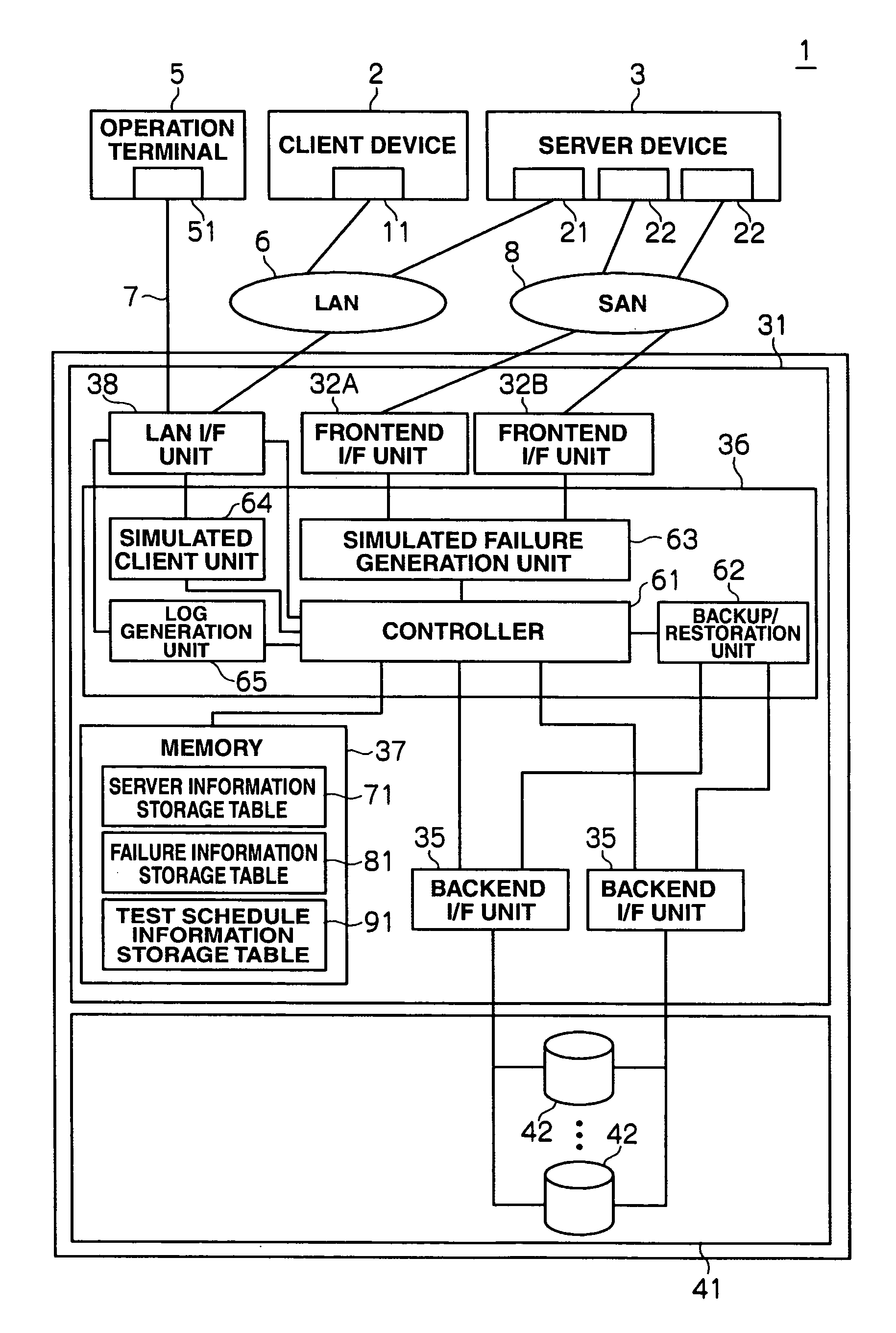
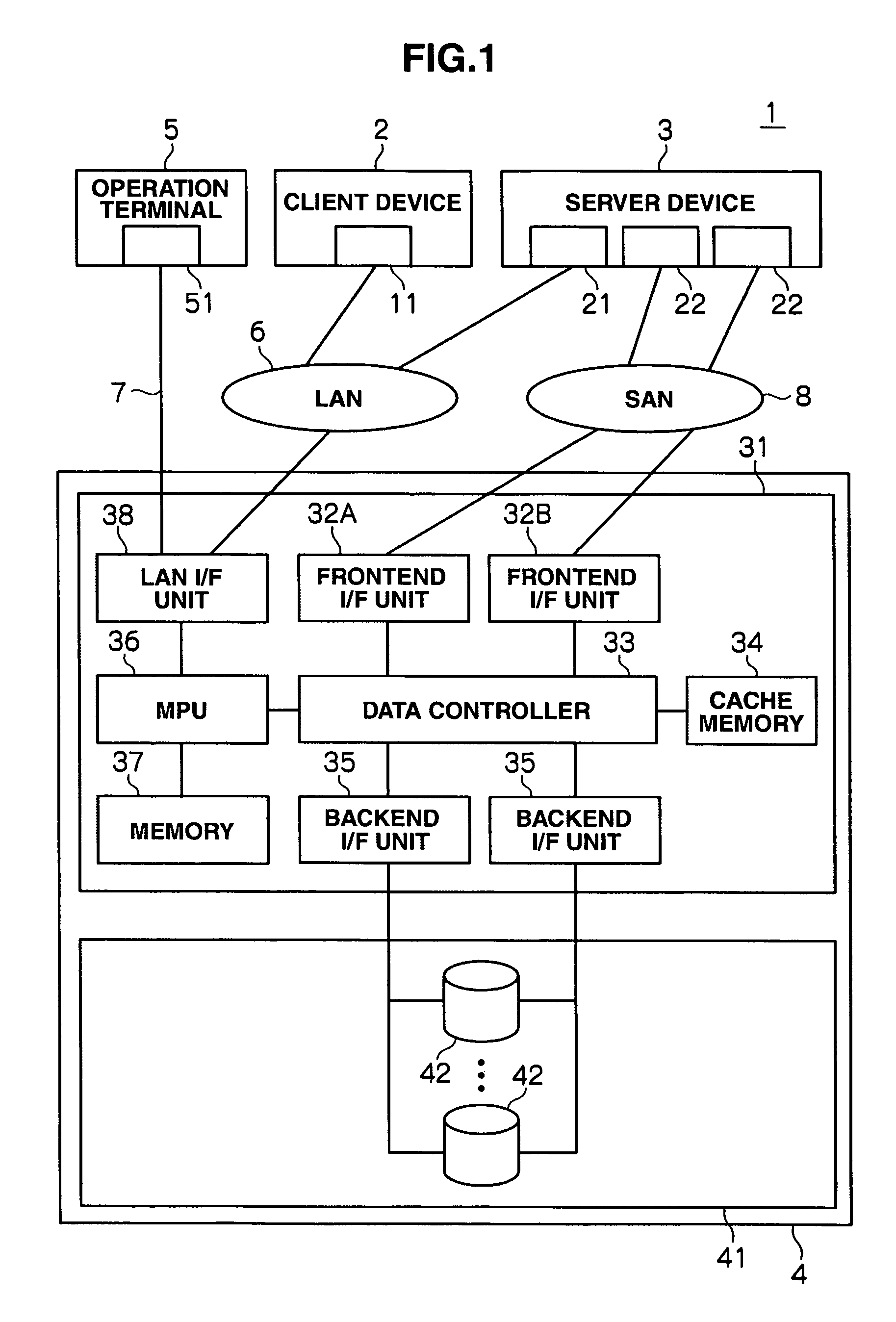
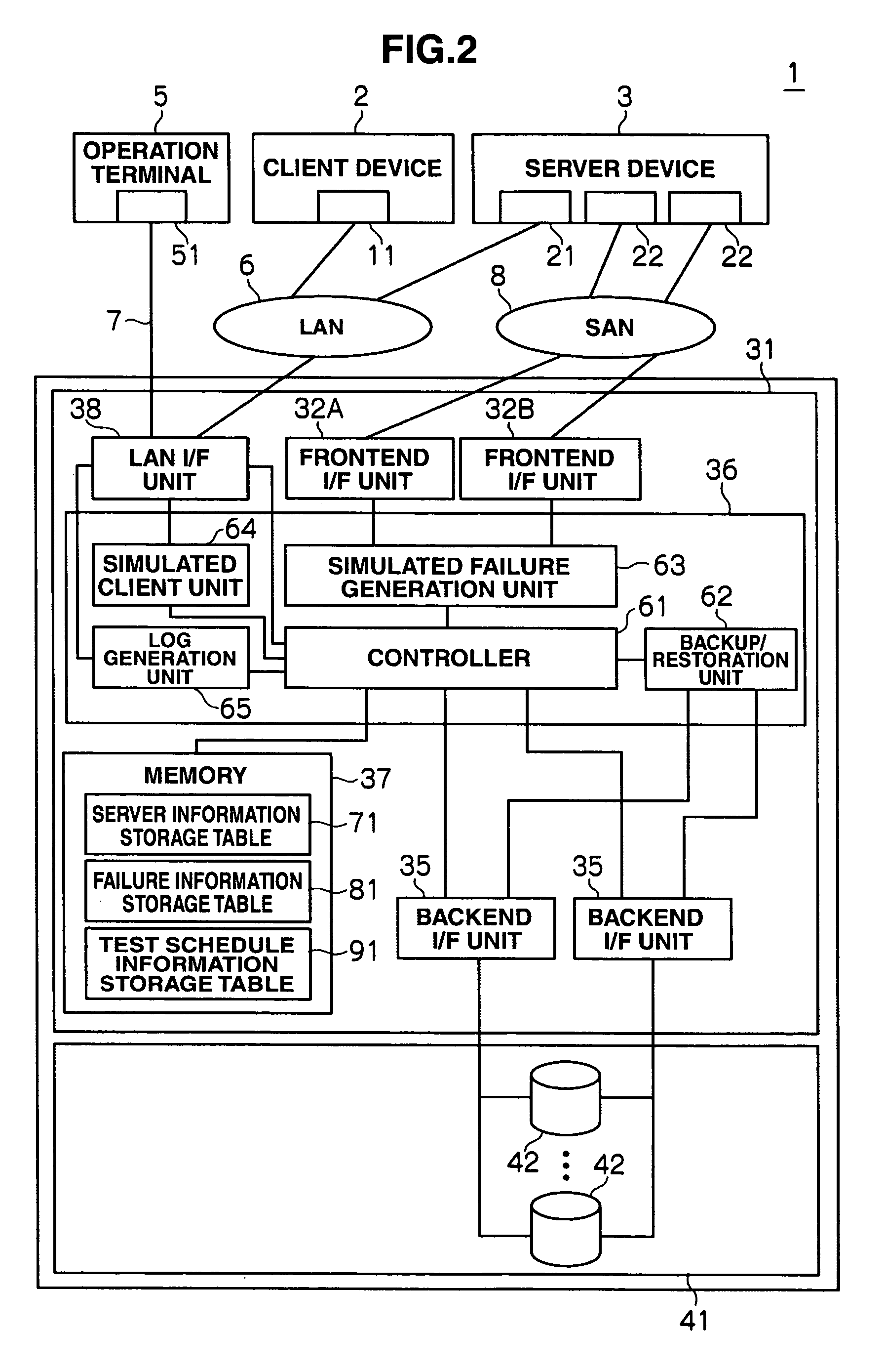
[0030]FIG. 1 shows the system configuration of a storage system 1 according to the present embodiment. This storage system 1 has a client device 2, a server device 3, a disk array device 4 and an operation terminal 5.

[0031]Here, this storage system 1 is configured by the client device 2, server device 3 and disk array device 4 being connected via a LAN (Local Area Network) 6, the disk array device 4 and operation terminal 5 being connected via the LAN 7, and the server device 3 and disk array device 4 being connected via a SAN (Storage Area Network) 8.

[0032]Incidentally, with this storage system 1, although a case is explained where the LAN 6 and LAN 7 are configured separately, the present invention is not limited thereto, and, for instance, these may be configured from a single LAN, and the client device 2, server...


PUM


Abstract

This disk array device having at least one volume that reads and writes data based on an access request transmitted from a client device via a server device, includes: a failure generation unit for generating a simulated failure in one's own device; an access request transmission unit for transmitting the access request transmitted from the client device to the server device; and a verification unit for verifying the setting of the server device regarding the response to the failure based on the response of the server to the access request transmitted from the access request transmission unit in a state of where the failure is being generated with the failure generation unit.

Description

CROSS-REFERENCES TO RELATED APPLICATIONS[0001]This application relates to and claims priority from Japanese Patent Application No. 2005-313499, filed on Oct. 27, 2005, the entire disclosure of which is incorporated herein by reference.BACKGROUND OF THE INVENTION[0002]The present invention generally relates to a disk array device and a failure response verification method thereof, and in particular relates to a disk array device suitable for reading and writing data based on an access request transmitted from a client device via a server device.[0003]Conventionally, a storage system which, by connecting a server device, which is connected to a plurality of client devices, and a disk array device, transmits an access request from the client device to the disk array device via the server device, stores the data in a physical disk of the disk array device according to the access request, or reads the data from such physical disk is becoming widely prevalent.[0004]Here, with this storage...

Claims


Application Information

Patent Timeline
Patent Type & Authority Patents(United States)
IPC IPC(8): G06F11/00
CPCG06F11/2221
Inventor KOSUGE, SHOICHIITTO, TAKAHIROTAMURA, AKIYORIOKADA, KOICHI
Owner GOOGLE LLC
Learn More