Method and device for atomizing liquid
a liquid atomization and liquid technology, applied in the direction of machines/engines, combustion air/fuel air treatment, combustion gas purification/modification, etc., can solve the problems of scarce heating of unvaporized liquid and short time of unvaporized liquid, and achieve low propagation rate, effective atomization of liquid, and simple and effective way
- Summary
- Abstract
- Description
- Claims
- Application Information
AI Technical Summary
Benefits of technology
Problems solved by technology
Method used
Image
Examples
first embodiment
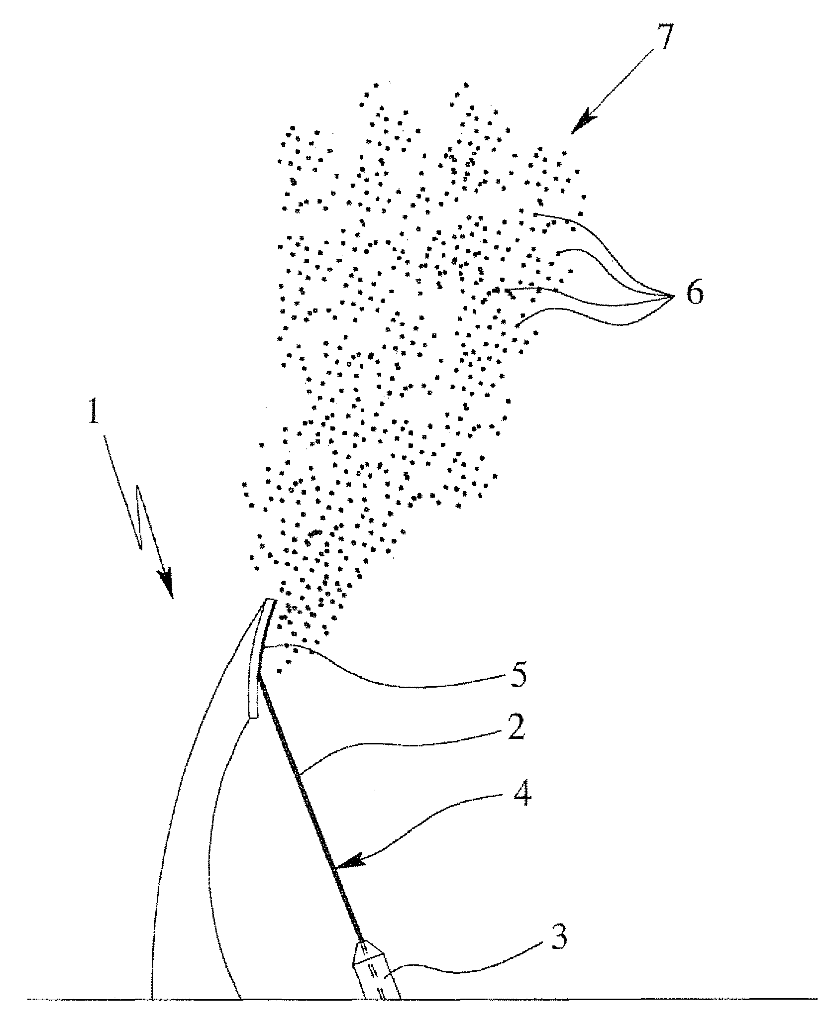
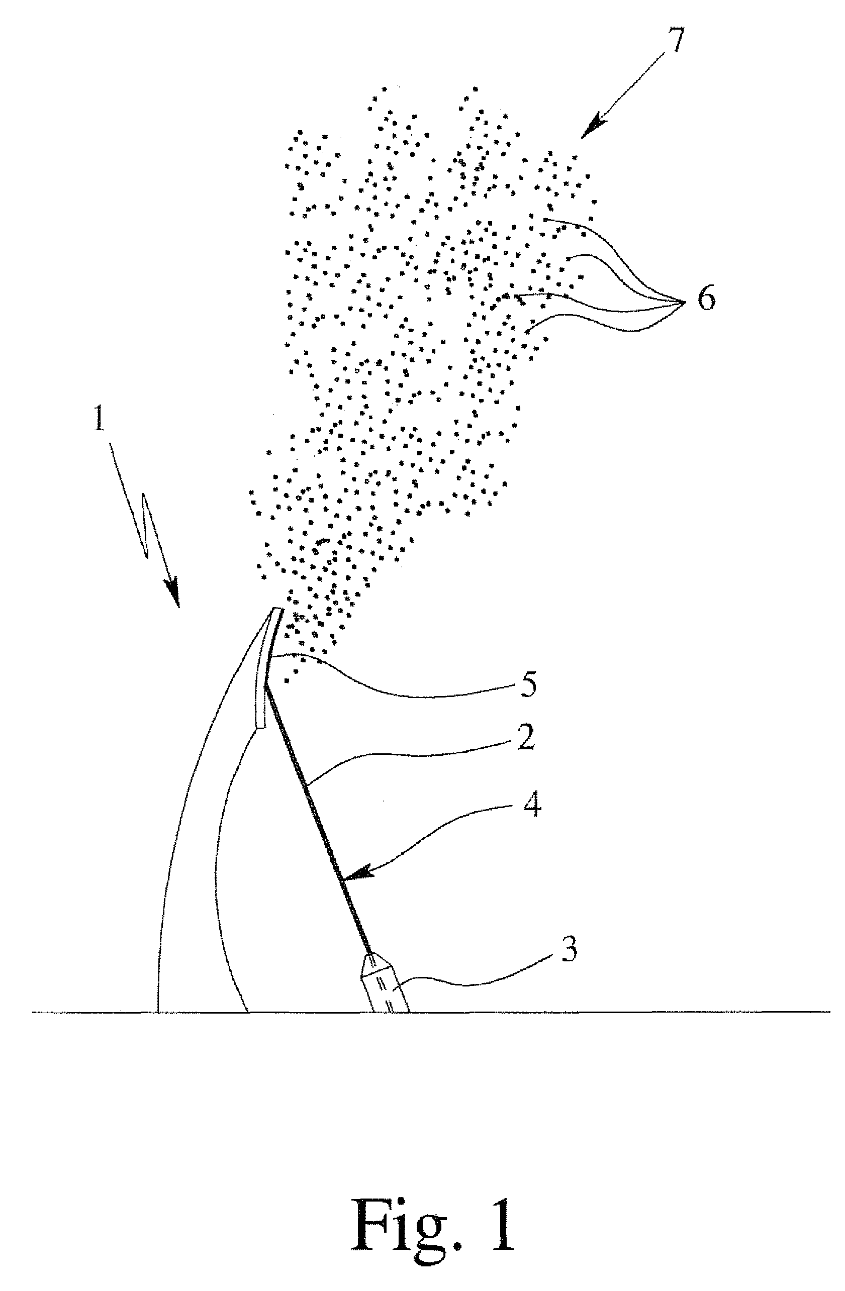
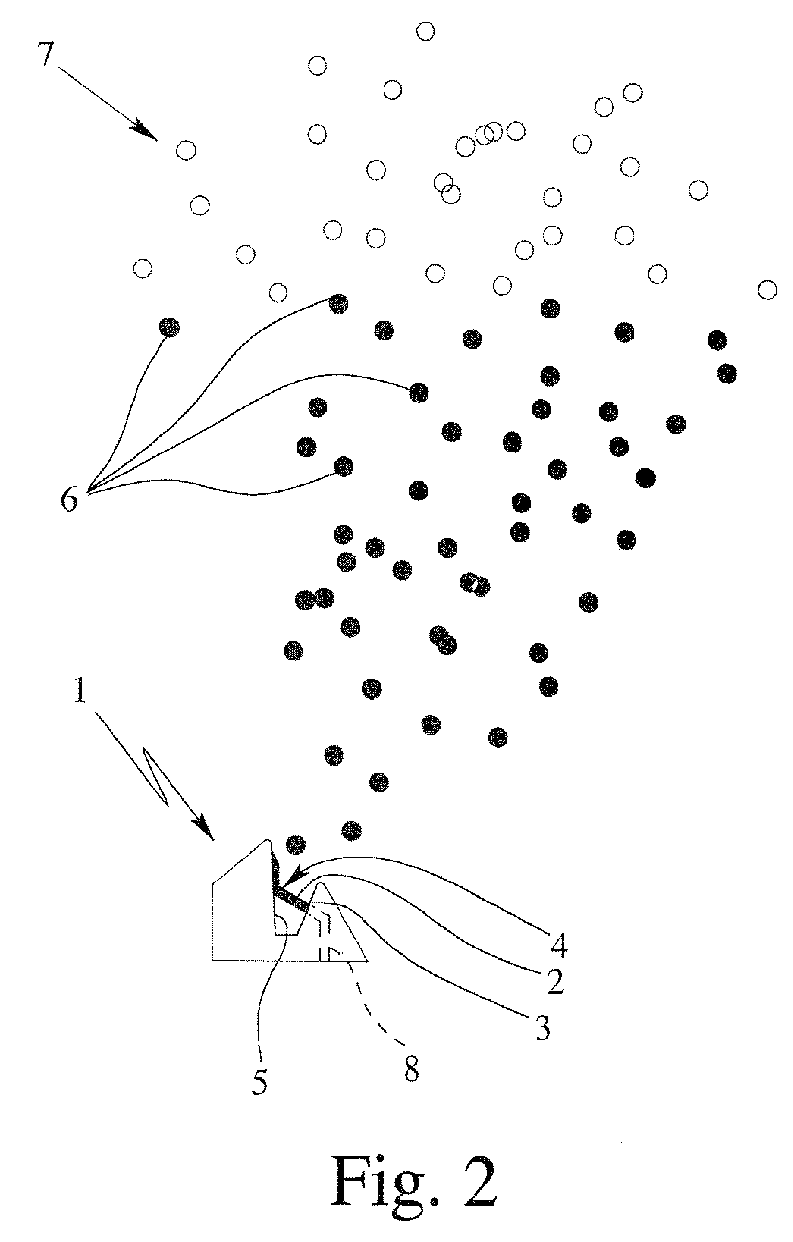
[0039]The schematic diagram according to FIG. 1 diagrammatically shows a device 1 in accordance with the invention. The device 1 serves for the atomization of a liquid 2, in particular, a liquid medicament formulation in the sense mentioned in the introduction, a cosmetic agent, an industrial liquid, or the like.
[0040]The device 1, preferably, comprises a nozzle 3 for generating a jet 4 of the liquid 2. In particular a free, i.e., non-laterally-directed jet 4, is formed. The jet 4, preferably, has an at least substantially circular cross-section with a diameter of, in particular, 1 to 50 μm, especially, less than 20 μm or even less than 10 μm. The jet 4 is ejected from the nozzle 3, preferably, at a pressure of 0.05 to 3 MPa, in particular, 0.1 to 0.3 MPa.
[0041]Furthermore, the device 1 comprises a hot or heatable contact surface 5 on which the jet 4 is incident.
[0042]The contact surface 5 may, in principle, have any suitable shape that is appropriate for the desired atomization, an...
second embodiment
[0081]In addition, the device 1 comprises a plurality of nozzles 3 that generate preferably at least substantially jets of the liquid 2 which, in particular, impact at different regions on the preferably common contact surface 5. The nozzles 3 are, in this embodiment, preferably provided with the liquid 2 via separate feed lines 8.
[0082]Furthermore, FIG. 3 shows a heating device 9 with electrical connections 10 that is associated with the contact surface 5. The heating device 9 is electrically operated and forms, possibly directly or with an appropriate coating, protective layer or the like, the contact surface 5.
[0083]FIG. 4 shows in a perspective view a third embodiment of the device 1 according to the proposal with only one nozzle 3. The nozzle 3 and the contact and deflecting surface 5 are, in this case, also formed as a common—preferably multipart—structural part corresponding to the second embodiment.
[0084]The feed line 8 for the liquid 2 to the nozzle 3 has a plurality of pa...
fifth embodiment
[0102]FIG. 6 shows in a schematic, section-like view a device 1 in the form of an inhaler according to the present invention.
[0103]The liquid 2 is stored in a container 16 and can be ejected through nozzle 3 as a jet 4 onto the heated contact surfaces 5 to partially vaporize the liquid 2 and form the aerosol 7 as explained above in connection with the other embodiments. The aerosol 7 is discharged via an optional mouthpiece 17.
[0104]The device 1 / inhaler comprises, preferably, a supply means or pump 18. In the present case, the pump 18 comprises a supply tube 19, which is preferably connected with container 16 and extends into container 16 and into the liquid 2. The supply tube 19 extends with its other end into a pump chamber 20 and acts as a pump piston. A check valve 21 is preferably provided at the end of the supply tube 19 extending into the pump chamber 20.
[0105]The device 1 or pump 18 further comprises a preferably manually operated actuator 22. Preferably, the actuator 22 can...
PUM
| Property | Measurement | Unit |
|---|---|---|
| diameter | aaaaa | aaaaa |
| length | aaaaa | aaaaa |
| temperature | aaaaa | aaaaa |
Abstract
Description
Claims
Application Information
 - R&D
- Intellectual Property
- Life Sciences
- Materials
- Tech Scout
- Unparalleled Data Quality
- Higher Quality Content
- 60% Fewer Hallucinations
Browse by: Latest US Patents, China's latest patents, Technical Efficacy Thesaurus, Application Domain, Technology Topic, Popular Technical Reports.
© 2025 PatSnap. All rights reserved.Legal|Privacy policy|Modern Slavery Act Transparency Statement|Sitemap|About US| Contact US: help@patsnap.com


