Hydraulic controlling apparatus for automatic transmission for vehicle

a technology of automatic transmission and hydraulic control apparatus, which is applied in mechanical devices, transportation and packaging, gearing, etc., can solve the problems of inability to run the vehicle, all solenoid valve devices are brought into failure, and the driver may have a sense of incongruity

Active Publication Date: 2009-11-03
TOYOTA JIDOSHA KK
View PDF13 Cites 8 Cited by
  • Summary
  • Abstract
  • Description
  • Claims
  • Application Information

AI Technical Summary

Benefits of technology

[0019]Accordingly, different from the case where establishing the high-speed side fail-safe gear step uniformly for the failure occurrence upon the vehicle running in the low-speed side gear step, lack of the driving force is avoided to secure the suitable vehicle running after stoppage. In addition, different from the case of establishing the low-speed side fail-safe gear step uniformly for the failure occurrence upon the vehicle running in the high-speed side gear step, sense of incongruity by the driver resulted from extremely increased rotation speed of the engine exceeding the excessive rotation area and strong engine brake is avoided to secure the suitable vehicle running after the failure occurrence.
[0023]Specifically, the normal / failure switching valve (i) in the normal-side position thereof allows the output hydraulic pressure from the first solenoid pressure regulation valve to be supplied to the first hydraulic type frictionally engaging device, from the second solenoid pressure regulation valve to be supplied to the second hydraulic type frictionally engaging device, and from the third solenoid pressure regulation valve to be supplied to the third hydraulic type frictionally engaging device, and (ii) in the failure-side position thereof allows the hydraulic pressure for forward running from the fail-safe gear step switching valve to be supplied to the first hydraulic type frictionally engaging device or second hydraulic type frictionally engaging device, and the base pressure or the hydraulic pressure for forward running to be supplied to the third hydraulic type frictionally engaging device.
[0033]The hydraulic controlling apparatus including the hydraulic type frictionally engaging devices is preferably provided with, as the solenoid valve device, for example plural solenoid pressure regulation valves of which output hydraulic pressure is directly supplied to a hydraulic pressure actuator (hydraulic pressure) of the hydraulic type frictionally engaging devices for increase of the response. However, instead thereof, a shift control valve corresponding to each of the solenoid valves are provided so that an output hydraulic pressure thereof is used as a pilot hydraulic pressure for allowing the operation oil from the control valve to hydraulic pressure actuator. In such case only the pilot pressure being outputted, due to small oil amount of the control output, the linear solenoid can be made compact, compared to the case where the output hydraulic pressure is directly supplied to hydraulic type frictionally engaging device.

Problems solved by technology

By the way, there may be an off-fail where the command signals from the electronic controlling apparatuses do not reach to the solenoid valve device for some reasons such as a wire malfunction or a disengagement of a connector, so that all of the solenoid valve devices are brought into failure state to stop operation thereof.
In such failure state, there may be a fear that the hydraulic type frictionally engaging devices are not brought into the engaged state, resulting in that the speed-change step of the automatic transmission is not established to make the vehicle running impossible.
However, in the above conventional art, there may arise a drawback, when the shift lever is shifted from a “D” position to a “N” position, and then is shifted to the “D” position again, in the failure state of all the solenoid valve devices.
As a result, when the D→N→D operation of the shift lever is preformed during the vehicle running in high speed, a driver may have a sense of incongruity.

Method used


Image

  • Hydraulic controlling apparatus for automatic transmission for vehicle
  • Hydraulic controlling apparatus for automatic transmission for vehicle
  • Hydraulic controlling apparatus for automatic transmission for vehicle

Examples


Embodiment Construction

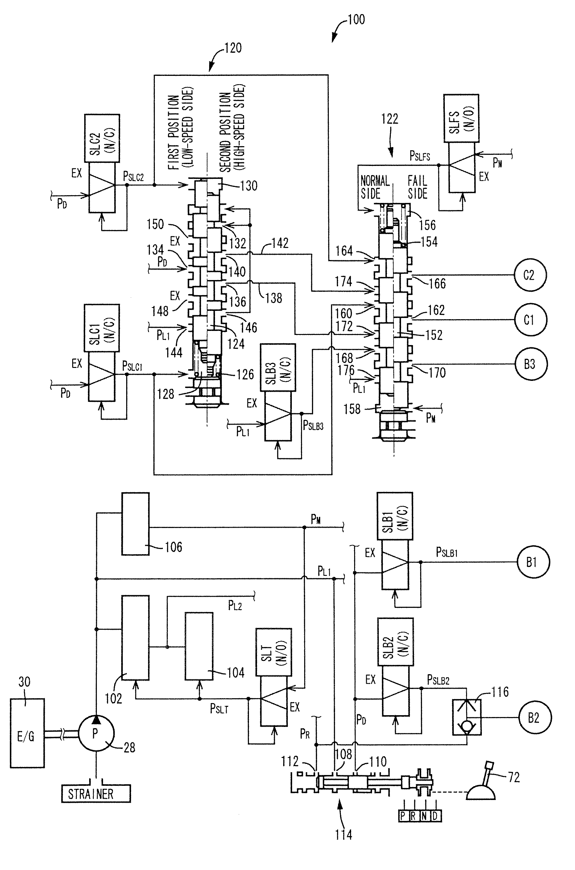
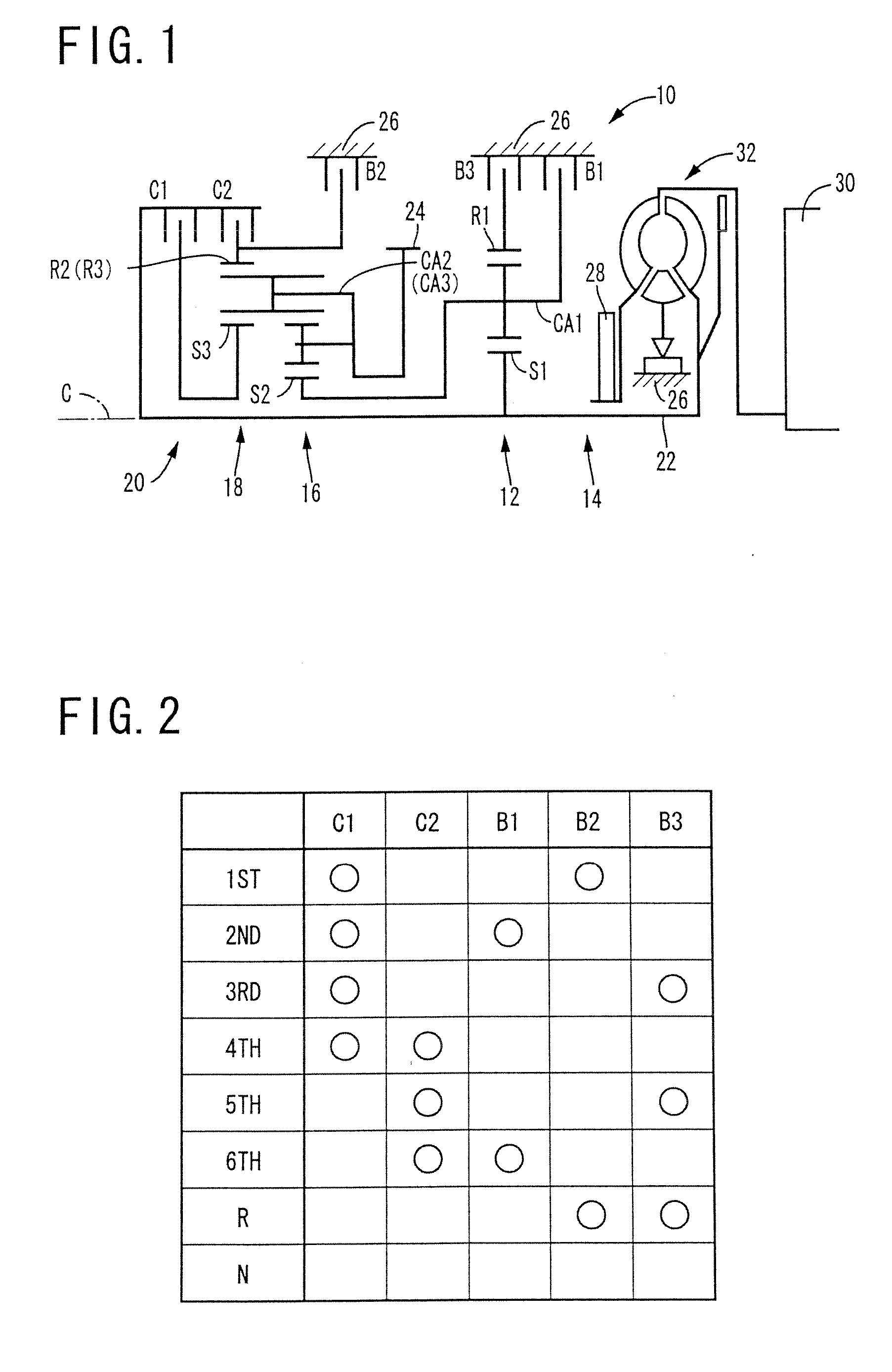
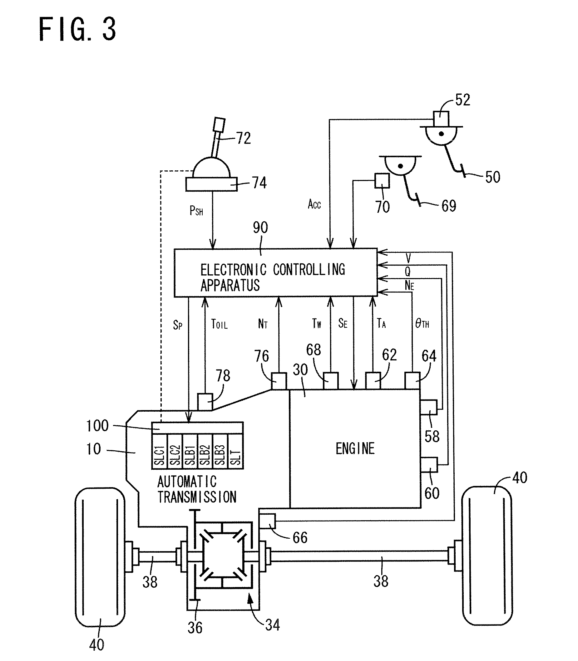
[0041]In the following, an embodiment of the present invention will be explained with reference to attached drawing. FIG. 1 is a framework view explaining structure of an automatic transmission for vehicle (hereinafter briefly referred to an “automatic transmission”) 10 to which the present invention is applied, and FIG. 2 is an operation table explaining frictionally engaging elements i.e., frictionally engaging devices for establishing plural speed-change steps. This transmission 10 is preferably mounted on a front engine, front drive type vehicle in a lateral direction i.e., right-left direction. In a transmission casing 26 as a non-rotatable member to be fixed to a vehicle body, a first speed-change part 14 and a second speed-change part 20 are mounted on a common shaft having a common axis C. The first speed-change part 14 is mainly comprised of a first planetary gear unit 12 of single pinion type, while the second speed-change part 20 has a predetermined type which is mainly c...


PUM


Abstract

The fail-safe gear step switching valve (120) can be switched to the first position to establish the low-speed side fail-safe gear step (third speed-change gear step) or the second position to establish the high-speed side fail-safe gear step (fifth speed-change gear step). Upon the failure state of the solenoid valve device (SLC1, SLC2), the fail-safe gear step switching valve is held at the second position by the line hydraulic pressure (PL1). Two kinds of the fail-safe gear steps i.e., the third speed-change gear step and the fifth speed-change gear step can be established depending on the vehicle state just before the failure occurrence of the fail-safe gear step switching valve. Even if the D→N operation of the shift lever (72) is performed during the vehicle running in the fifth speed-change gear step, the fail-safe gear step switching valve remains at the second position to establish the fifth speed-change gear step even upon the shifting operation of the shift lever to the “D” position again.

Description

[0001]The present application is based on Japanese Patent Application No. 2005-338942 filed on Nov. 24, 2005, the content of which is incorporated herein by reference.BACKGROUND OF THE INVENTION[0002]1. Field of the Invention[0003]The present invention relates to a hydraulic controlling apparatus for an automatic transmission for vehicle in which speed-change steps are established by selectively operating hydraulic type frictionally engaging device by a solenoid valve device. In particular, it relates to a fail-safe technique for allowing the vehicle rung even in a failure state of the solenoid valve device.[0004]2. Description of Related Art[0005]In an automatic transmission, one of plural speed-change steps is established in a alternative way by a hydraulic controlling apparatus. The hydraulic controlling apparatus includes plural hydraulic type frictionally engaging devices such as clutches and brakes, and a solenoid valve device for selectively operating the hydraulic type contr...

Claims


Application Information

Patent Timeline
Patent Type & Authority Patents(United States)
IPC IPC(8): F16H31/00F16H61/12F16H61/68F16H61/684F16H61/686
CPCF16H61/12F16H3/663F16H61/686F16H2061/1232F16H2200/0052Y10S477/906F16H2200/2023F16H2200/2043F16H2061/1236F16H2061/1264Y10T477/691F16H2200/2007
Inventor FUKUSHIMA, HIROSHIKATO, NAOKITSUCHIDA, KENICHI
Owner TOYOTA JIDOSHA KK
Why Eureka
Try Eureka