Foil-type pressure sensor

a pressure sensor and oil-type technology, applied in the field of oil-type pressure sensors, can solve the problems of electromagnetic interference becoming a serious issue, the production tolerance or the dynamic range the influence of bending of the sensor is reduced, so as to achieve optimal coupling efficiency and reduce the influence of bending of the sensor

Inactive Publication Date: 2009-11-03
IEE INT ELECTRONICS & ENG SA
View PDF7 Cites 37 Cited by
  • Summary
  • Abstract
  • Description
  • Claims
  • Application Information

AI Technical Summary

Benefits of technology

[0008]The present sensor hence is based on variable attenuation of the light propagating through the sensing region. The skilled person will appreciate that such a sensor is fairly insensitive to electromagnetic interference with other electronic devices as it is based on optical detection. Reliable detection is thus enabled also in electromagnetically “noisy” environment. Compared to traditional foil-type pressure sensors, the present invention has the further advantage of a simpler production.
[0010]When optical waveguides used for transmitting light to or from the sensing region bend or are subjected to stress, they can thereby induce additional losses, which could cause an erroneous pressure determination. A reference waveguide, positioned substantially parallel to the input waveguide and / or the output waveguide, is preferably used. The reference waveguide is not interrupted between the light source and the light detector, as opposed to the input and output optical waveguides in the sensing region. The reference waveguide undergoes substantially the same bending and stress as the other waveguides, which allows determining the light intensity losses in the waveguides. The light intensity detected by the light detector can thus be normalised and the sole pressure effect be determined. Use of a reference waveguide is especially well suited when a relative light intensity or light flux measurement is preferred over an absolute measurement. In the context of waveguide bending, it shall be noted that there are pressure sensors, which are based on light attenuation caused by bending of a waveguide. Deformation of the waveguide is necessary for operation of these sensors. In the present foil-type pressure sensor the waveguide can be protected against deformation and stress, which can lead to a longer sensor lifetime.
[0014]The light emitting means and / or the light collecting means preferably comprise optics adapted for optimal coupling efficiency between the light emitting means and the light collecting means. When using optical waveguides, the numerical apertures of the input and output optical waveguides are advantageously chosen such that the coupling efficiency from input to output optical waveguide is optimal for the unloaded sensor. The optics may also comprise a lens associated with the light emitting means. The beam divergence can thereby be adjusted. If requested, a collimated beam can be shaped in the sensing region. An important advantage of the present sensing technique can be the reduced influence of bending of the sensor as a whole. In order to achieve that, the beam geometry can be adjusted in such a way that the coupling between input and output optical waveguides does not change significantly in response to sensor bending. This can e.g. be done by a light beam, which covers more than the end surface of the output waveguide. When the sensor slightly bends, the beam moves relatively to the output waveguide, but the amount of light coupled into it remains almost constant.

Problems solved by technology

This can constitute a drawback in certain applications, e.g. when relatively small pressures are to be detected.
Several options exist, which enable sensing of small pressures, e.g. reducing the spacer thickness, but they involve considerable constraints with regard to production tolerances or reduce the dynamic range of the sensor.
With the increasing number of electronic components, electromagnetic interference has become a serious issue in the development of electronic car equipment.

Method used


Image

  • Foil-type pressure sensor
  • Foil-type pressure sensor
  • Foil-type pressure sensor

Examples


Embodiment Construction

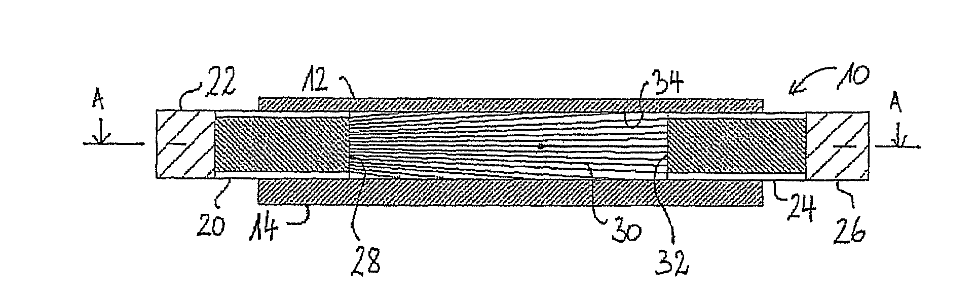
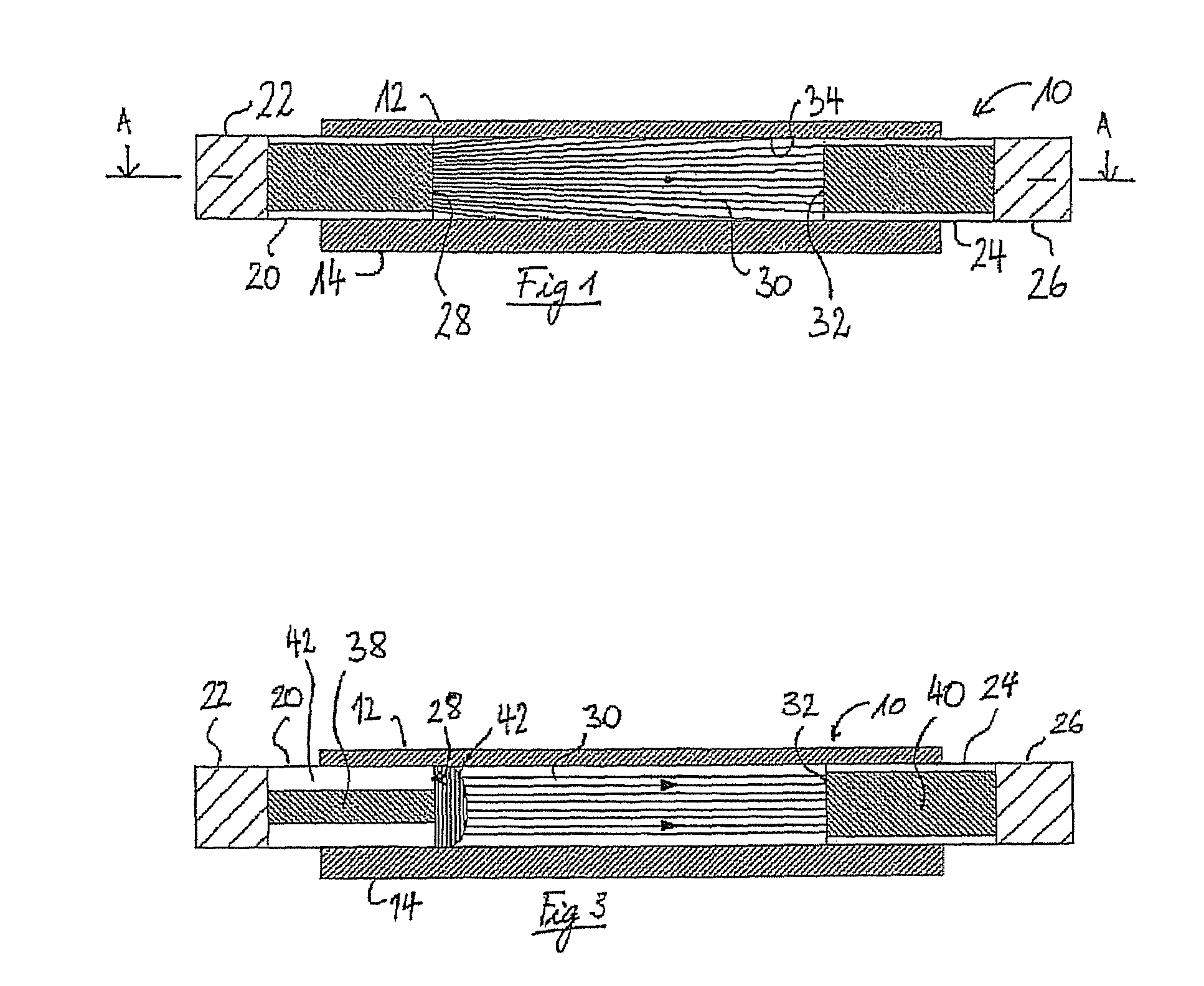
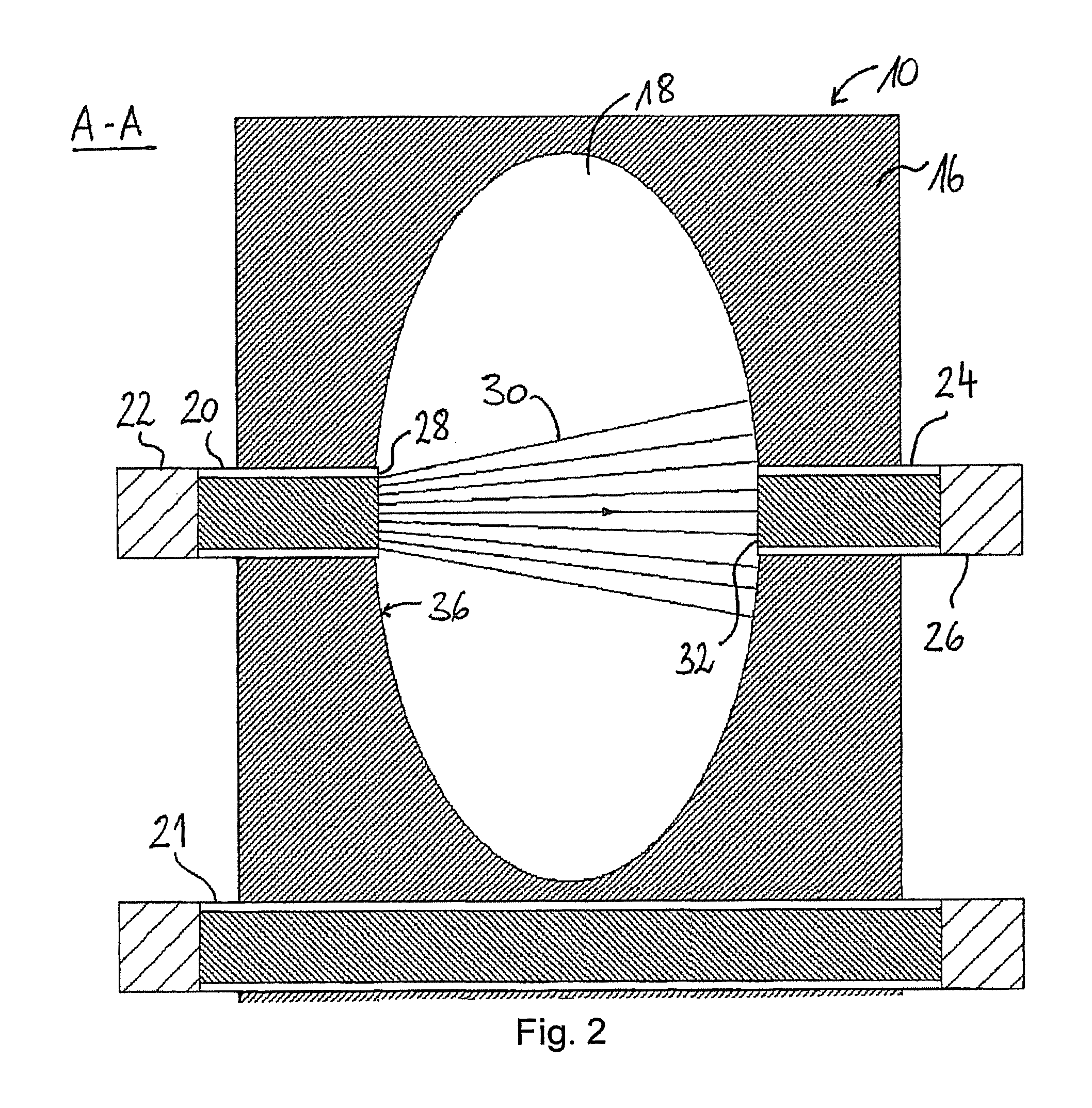
[0020]FIGS. 1 and 2 show cross-sectional views of a pressure sensor 10 in unloaded condition. The pressure sensor 10 comprises a first flexible foil 12 and a second foil 14, which is significantly less flexible than the first foil 12 and thicker. The foils 12, 14 sandwich a spacer 16, which keeps the foils 12, 14 at a certain distance from each other. The spacer 16 presents an opening, which defines a sensing region 18 of the pressure sensor 10. Embedded into the spacer 16 is an input optical waveguide 20, which guides light coming from a light source 22 into the sensing region 18. An output optical waveguide 24 is arranged substantially aligned with the input optical waveguide 20, on the opposed side of the sensing region 18. The output optical waveguide 24 is optically connected to a light intensity detector 26. The thickness of the spacer 16, i.e. the height of the sensing region corresponds to at least the diameter of the waveguides or fibres 20, 24, which typically is comprised...


PUM


Abstract

A foil-type pressure sensor includes a first foil and a second foil. A spacer is arranged in between the first and second foils, which keeps the foils at a certain distance from each other. The spacer presents an opening that defines a sensing region. In this sensing region, the first and second foils can be brought closer one to the other against the resiliency of the foils by pressure acting on the pressure sensor. The pressure sensor further includes light emitting means arranged between the foils for inputting light into the sensing region and light collecting means arranged between the foils for collecting light propagated from the light emitting means through at least part of the sensing region to the light collecting means. When the first and second foils are brought closer one to the other, at least one of the first and the second foils at least partially blocks light propagation through the sensing region.

Description

TECHNICAL FIELD OF THE INVENTION[0001]The present invention generally relates to foil-type pressure sensors.BRIEF DESCRIPTION OF RELATED ART[0002]Foil-type pressure sensors generally comprise two foils sandwiching a spacer. The spacer is provided with an opening or cutout, which defines a sensing region, in which the foils face each other at a distance corresponding to the spacer thickness. Known foil-type pressure sensors have at least two electrodes arranged in the sensing region. The foils are flexible and can be brought into contact with each other in the sensing region, in response to pressure acting on the foils. An electrical contact is thereby established between the two electrodes, and an electrical circuit is thereby closed. Preferably, a resistive or semiconductive layer is arranged in the sensing region to achieve that the electrical resistance between the electrodes gradually decreases when the contact surface between the foils increases. Such a pressure sensor is e.g. ...

Claims


Application Information

Patent Timeline
Patent Type & Authority Patents(United States)
IPC IPC(8): G01J1/04G01J1/56
CPCG01L1/24
Inventor KAISER, JEAN-LUC
Owner IEE INT ELECTRONICS & ENG SA
Why Eureka
Try Eureka