Floating wind turbine system

a floating wind turbine and wind power technology, applied in the direction of machines/engines, electric generator control, vessel construction, etc., can solve the problems of inconvenient installation of wind power generators, limited offshore technology, and high installation costs of offshore sites

Inactive Publication Date: 2009-11-03
VITERNA LARRY A
View PDF24 Cites 45 Cited by
  • Summary
  • Abstract
  • Description
  • Claims
  • Application Information

AI Technical Summary

Problems solved by technology

Such current offshore technology is limited to water depths of about 25 meters or less.
Installation costs for these offshore sites are significantly higher than on land because of the increased effort required while working on and in the water.
Accordingly, such concepts typically require large cranes for erection of the towers and turbines and are not optimal for wind turbines because of the large aerodynamic force in the direction of the wind as well as forces associated with dynamics from the angular momentum of the turbine blades.
Furthermore, wind and wave forces cause coupled motions of the support tower and the rotor blades, resulting in greater structural dynamic loads, deflections and stresses upon the wind turbine system.

Method used


Image

  • Floating wind turbine system
  • Floating wind turbine system
  • Floating wind turbine system

Examples


Embodiment Construction

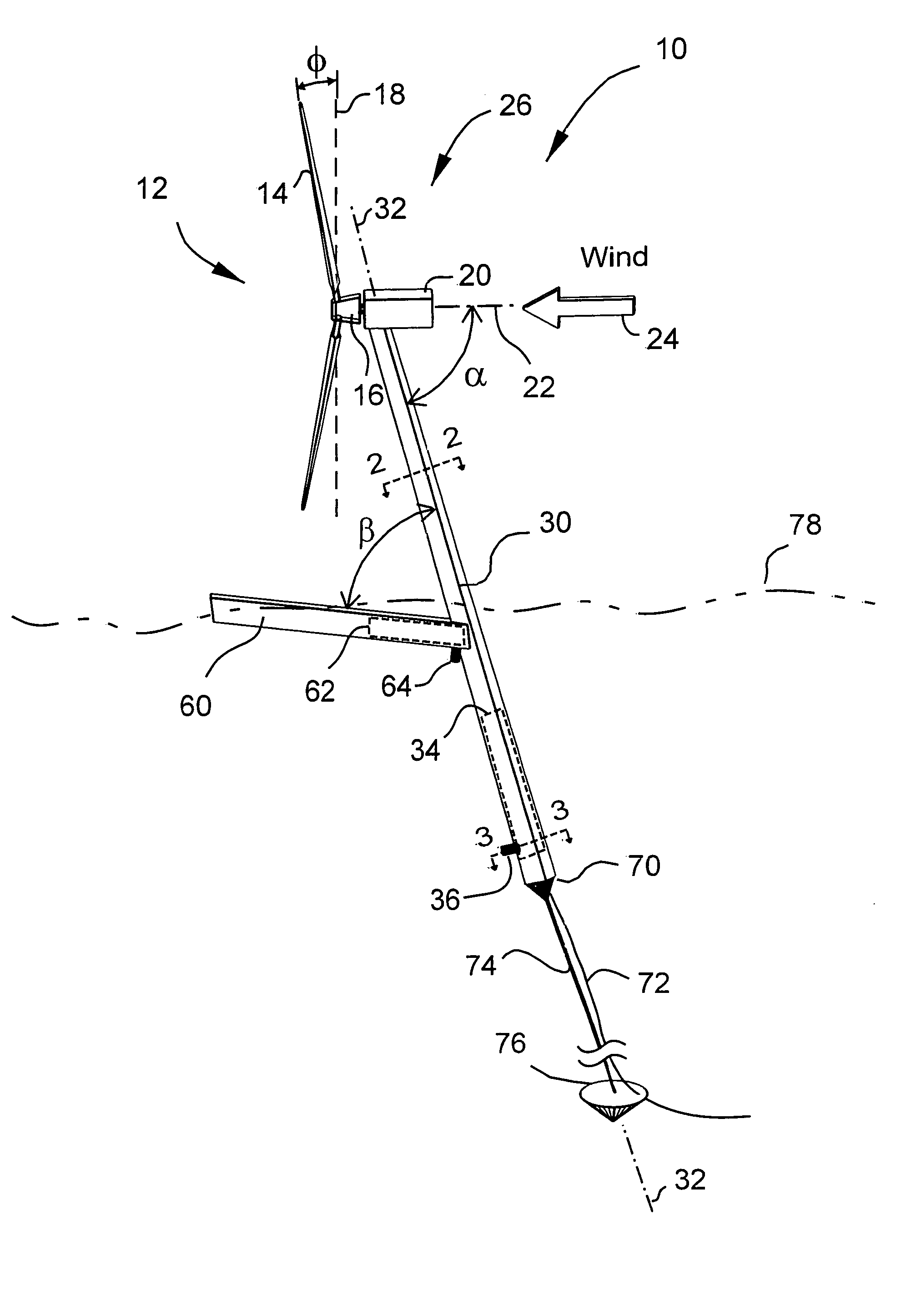
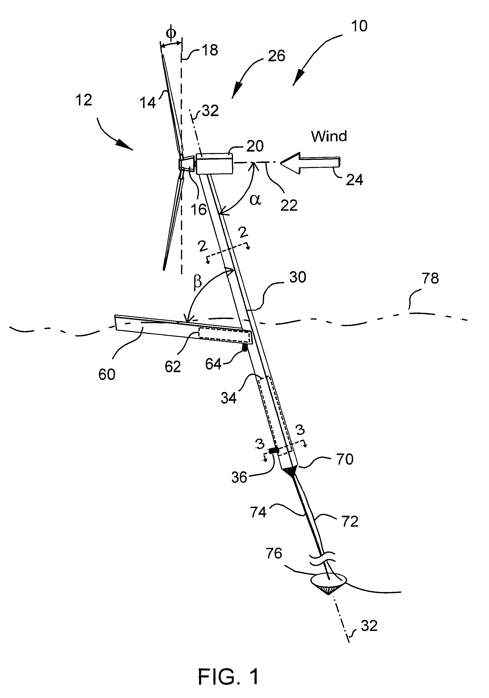
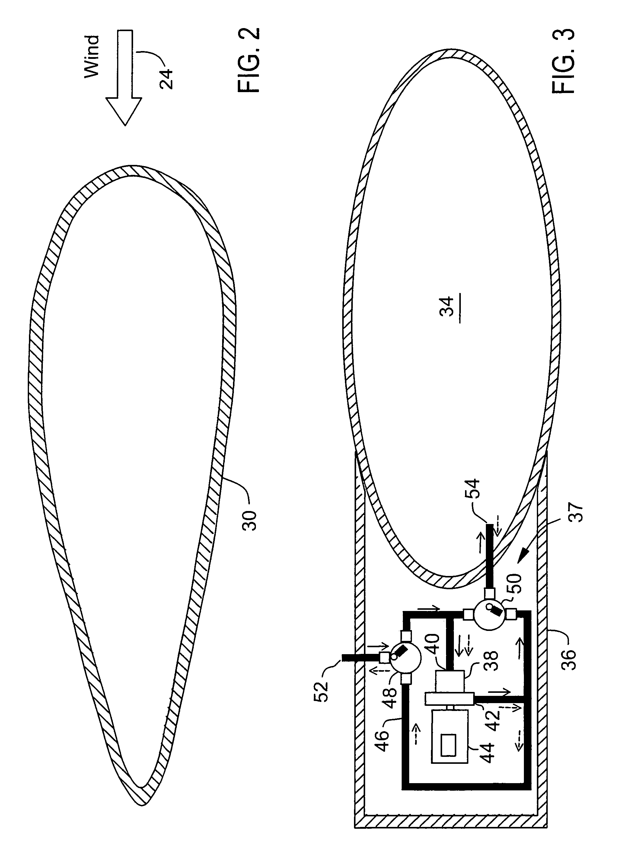
[0021]Presently preferred embodiments of the invention are shown in the figures identified above and described in detail below. It is emphasized that the drawings and description included herein are preferred embodiments and are not intended to limit the invention or claims. Instead, the intention is intended to cover all modifications, equivalents, and alternatives in the character and scope of the invention. In describing the preferred embodiment of the invention, common or similar characteristics are indicated by identical reference numerals, or in the absence of a reference numeral, are evident based upon the drawings or description. The figures are not necessarily to scale and may be shown exaggerated in scale for purposes of clarity and conciseness. The subject matter referred to using the terms “present invention,”“invention” and variations as used throughout this document are to mean one or more possible embodiments of the invention and are not intended to, and should not, l...


PUM


Abstract

A floating wind turbine system with a tower structure that includes at least one stability arm extending therefrom and that is anchored to the sea floor with a rotatable position retention device that facilitates deep water installations. Variable buoyancy for the wind turbine system is provided by buoyancy chambers that are integral to the tower itself as well as the stability arm. Pumps are included for adjusting the buoyancy as an aid in system transport, installation, repair and removal. The wind turbine rotor is located downwind of the tower structure to allow the wind turbine to follow the wind direction without an active yaw drive system. The support tower and stability arm structure is designed to balance tension in the tether with buoyancy, gravity and wind forces in such a way that the top of the support tower leans downwind, providing a large clearance between the support tower and the rotor blade tips. This large clearance facilitates the use of articulated rotor hubs to reduced damaging structural dynamic loads. Major components of the turbine can be assembled at the shore and transported to an offshore installation site.

Description

CROSS-REFERENCE TO RELATED APPLICATIONS[0001]This application claims the benefit of U.S. Provisional Application No. 60 / 978,155, filed Oct. 8, 2007, the disclosure of which is incorporated herein by reference.STATEMENT REGARDING FEDERALLY SPONSORED RESEARCH OR DEVELOPMENT[0002]Not applicable. The inventor is a federal employee at the National Aeronautics and Space Administration (NASA); however, the invention was conceived and reduced to practice by the inventor outside the scope of his official duties. A memorandum from the NASA Intellectual Property Counsel dated Sep. 20, 2007 states that: “Pursuant to 37 Code of Regulations, Section 501.7, it is the determination of NASA that title to the captioned invention shall remain with the federal employee inventor, Larry A. Viterna. NASA makes no claim to any rights in that invention.”BACKGROUND OF THE INVENTION[0003]This invention relates in general to wind turbine systems and in particular to a floating wind turbine system.[0004]Wind tu...

Claims


Application Information

Patent Timeline
Patent Type & Authority Patents(United States)
IPC IPC(8): F03B13/12
CPCB63B21/50B63B35/44F03D1/005F03D1/001B63B2021/505B63B2035/446Y02E10/727F05B2240/2213F05B2240/93F03D13/10F03D13/40Y02E10/72F03D1/00F05B2240/95F05B2240/96F03D13/20
Inventor VITERNA, LARRY A.
Owner VITERNA LARRY A
Why Eureka
Try Eureka