System and method for providing diffuse illumination in a symbology reader

a symbology reader and diffuse illumination technology, applied in the field of illumination, can solve the problems of obscuring the acquired image, inappropriate use of highly reflective bright field illumination, and inability to adapt to the use of a movable type of illuminator, so as to improve the collimation of radially directed light

Active Publication Date: 2009-11-10
COGNEX TECH & INVESTMENT
View PDF132 Cites 84 Cited by
  • Summary
  • Abstract
  • Description
  • Claims
  • Application Information

AI Technical Summary

Benefits of technology

[0017]In another embodiment, the grid assembly is illuminated by a surrounding circuit board having mounted thereon an encircling array of side-projecting LEDs that transmit light directly, radially into the perimeter edge of the grid assembly plate. The plate can include a lens-shaped edge for improved collimation of the radially directed light.
[0018]In another embodiment, the potential problem of varying image intensity about the field of view can be addressed by providing a polygonal (square, for example) aperture to the imager lens and arrangin

Problems solved by technology

Conversely, where a symbology or other subject is formed on a more-irregular surface, or is created by etching or peening a pattern directly on the surface, the use of highly reflective bright field illumination may be inappropriate.
A peened/etched surface has two-dimensional properties that

Method used


Image

  • System and method for providing diffuse illumination in a symbology reader
  • System and method for providing diffuse illumination in a symbology reader
  • System and method for providing diffuse illumination in a symbology reader

Examples


Embodiment Construction

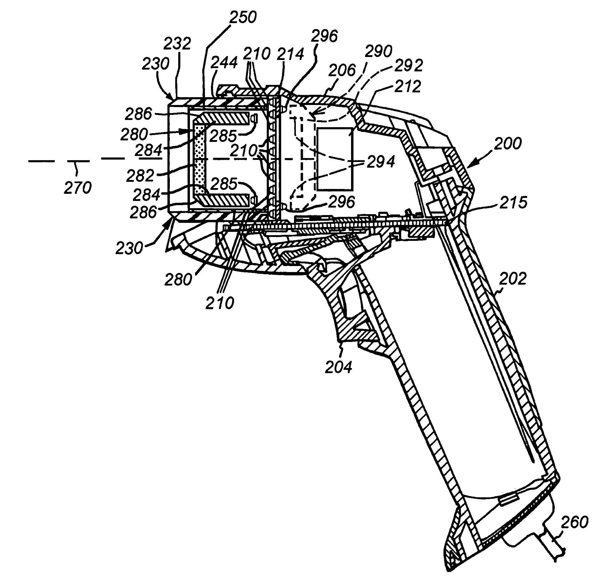
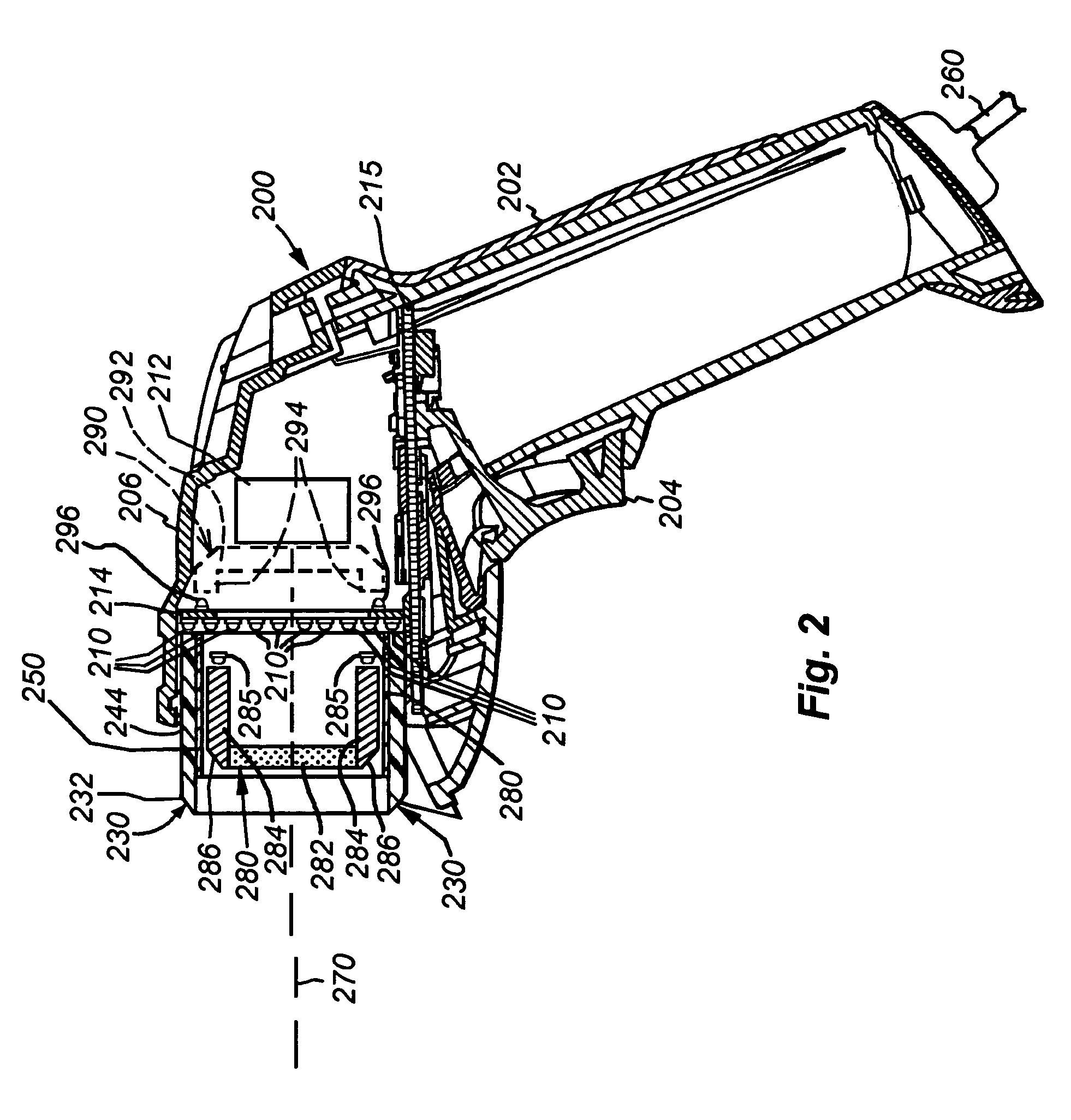
[0036]FIG. 2 shows a cross sectional side view of an illustrative embodiment of the reader 200 according to the present invention. The imager 212 and an illumination board 214 are positioned on a shock-resistant mounting (not shown) within the housing 206. In this exemplary embodiment, the processor module and related functional electronic components are mounted on a processor board 215. The grip portion 202 and the trigger 204 are functionally cooperative with the housing 206 and components of the processor board 215. The grip portion 202 includes a conveniently placed trigger 204 that can be actuated by a finger of the user to initiate the image acquisition and decoding function. More particularly, pressing the trigger causes each type and / or color of illumination used in the reader 200 to be projected onto the subject of interest (either in succession or simultaneously), and also causes corresponding acquisition of an image of the subject by the imager.

[0037]With further referenc...


PUM


Abstract

An illumination system and method for use in a handheld symbology reader that employs a grid of reflecting elements applied to a transparent plate adapted to project a highly diffuse and uniform illumination on a subject. The grid defines a geometry with a large number of transparent spaces between grid elements through which an image of the subject can be acquired. A light source array is configured to project light into the grid at a right angle via a light pipe having a distal beveled edge or side projecting light sources. Another light source may be employed to illuminate second light pipe with a chamfered edge to create low-angle illumination.

Description

BACKGROUND OF THE INVENTION[0001]1. Field of the Invention[0002]This invention relates to machine vision systems and symbology readers that employ machine vision and more particularly to illuminators for the same.[0003]2. Background Information[0004]Machine vision systems use image acquisition devices that include camera sensors to deliver information on a viewed subject. The system then interprets this information according to a variety of algorithms to perform a programmed decision-making and / or identification function. For an image to be most-effectively acquired by a sensor in the visible, and near-visible light range, the subject should be properly illuminated.[0005]In the example of symbology reading (also commonly termed “barcode” scanning) using an image sensor, proper illumination is highly desirable. Symbology reading entails the aiming of an image acquisition sensor (CMOS camera, CCD, etc.) at a location on an object that contains a symbol (a “barcode”), and acquiring an ...

Claims


Application Information

Patent Timeline
IPC IPC(8): G06K7/10
CPCG06K7/10732G06K7/10881G06K7/10831
Inventor NUNNINK, LAURENSEQUITZ, WILLIAM H.GERST, CARL W.
Owner COGNEX TECH & INVESTMENT
Why Eureka
Try Eureka