Spool for spinning reel

a spinning reel and spool technology, applied in the field of spools, can solve the problems of water intruding into the spool, and achieve the effect of light and compact spools

Active Publication Date: 2009-11-10
SHIMANO INC
View PDF17 Cites 5 Cited by
  • Summary
  • Abstract
  • Description
  • Claims
  • Application Information

AI Technical Summary

Benefits of technology

[0010]One object of the present invention is to successfully prevent liquid from entering into the circular recess formed in the front portion of the spool.
[0023]The spool, according to still a further aspect of the present invention, wherein the bobbin trunk includes a second housing recess that is formed with a substantially-circular opening rearward and where the drag mechanism further includes a rear friction portion that has a single or plurality of rear drag washer(s) that is / are accommodated in the second housing recess. In this case, the rear friction portion is disposed in the second housing recess that is disposed in the interior of the bobbin trunk. Accordingly, it is possible to achieve a light and compact spool.

Problems solved by technology

Therefore, even when a sealing member is attached between the drag regulation member and the spool, if water enters the interior of the drag regulation member through the gap, there is a possibility that water will also intrude into the drag washer side along the spool shaft that penetrates the center part of the drag regulation member.

Method used


Image

  • Spool for spinning reel
  • Spool for spinning reel
  • Spool for spinning reel

Examples


first embodiment

Modified Example of First Embodiment

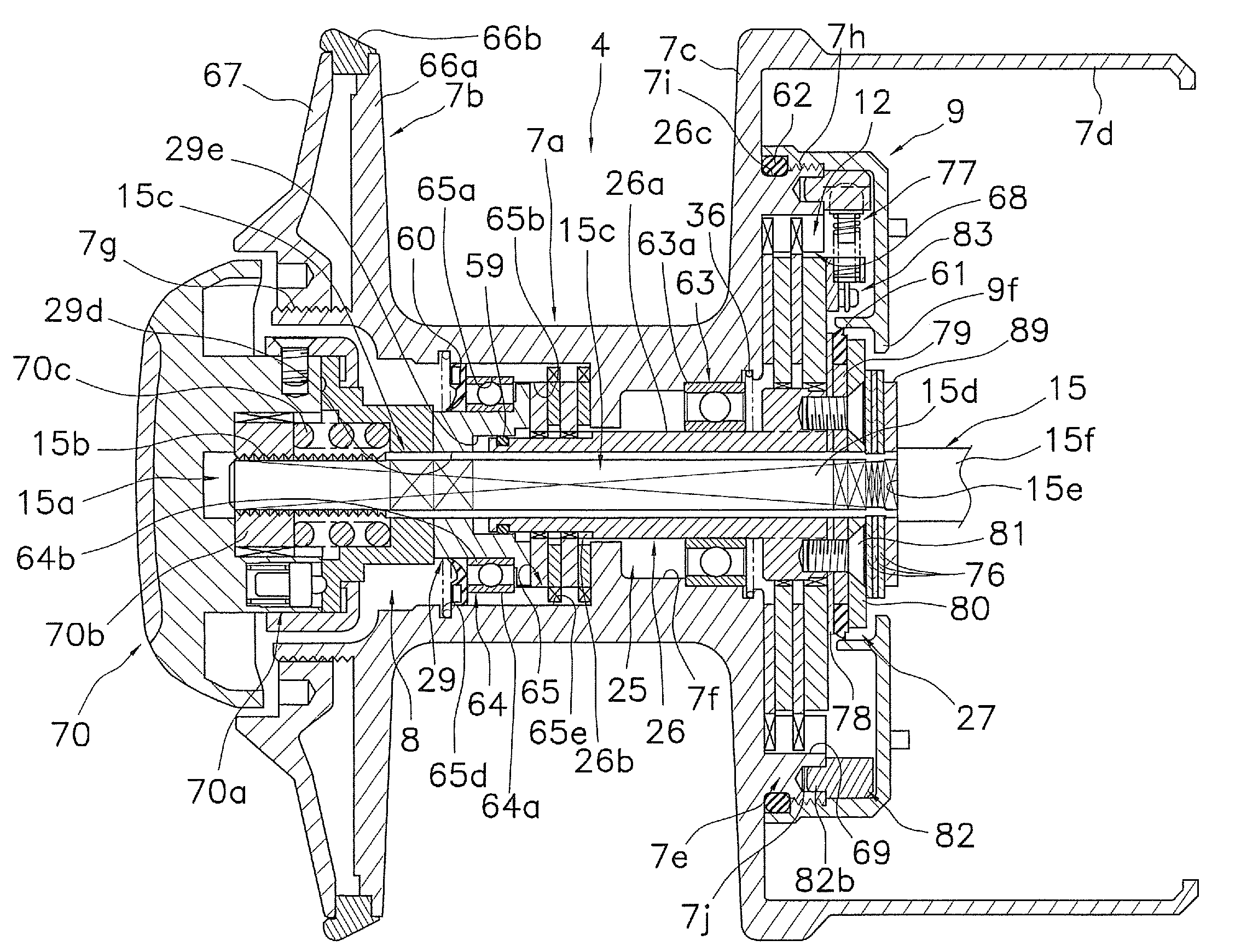
[0094]In the above described first embodiment, for the purpose of easily regulating the position of the spool 4 in the front-to-rear direction, the three regulation washers 76 are configured to be left on the spool shaft 15 when the spool 4 is removed from the spool shaft 15. However, as illustrated in FIG. 7, the three regulation washers 176 are disposed on the front of a restriction disk 179 to which a third sealing member 161 is mounted as illustrated in FIG. 7. The regulation washers 176 may be configured to be removed from the spool shaft 15 together with a spool 104. In addition, an inner periphery 109f of a disk portion 109b of a cover member 109 is not formed to protrude. The inner periphery 109f is arranged not to overlap a restriction disk 180 in the radial direction.

[0095]The restriction disk 180, which is fixed to a support member main body 126 by a screw member, is disposed on the rearmost of the spool 104. The restriction disk 180 ma...

second embodiment

Modified Example of Second Embodiment

[0129]According to the second embodiment, the first friction portion 271 of the drag mechanism 208 is made up of four drag washers: the press washer 229, the first drag washer 286, and the second drag washers 287a and 287b. The second friction portion 272 is made up of the single washer portion 226b of the support body 226. However, the present invention is not limited to this.

[0130]Note that a configuration of the modified example, which is almost the same as that of the second embodiment, will be omitted in the following explanation.

[0131]As illustrated in FIGS. 11 and 12, an inner tubular portion 365e is formed on the inner peripheral side of a partition portion 365c of a bobbin trunk 307a of a spool body 307, and protrudes forward and rearward. Anti-rotation grooves 365f and 365g are formed on the front part and the rear part of the inner tubular portion 365e along the diameter direction so as to penetrate through the inner and outer peripher...


PUM


Abstract

A spool of a spinning reel includes a support member, a spool body, a drag mechanism, a first sealing member, and a second sealing member. The support member is detachably connected to a spool shaft. The spool body includes a housing recess that is frontally open and rotatably attached to the support member. The drag mechanism decelerates the spool body and includes a front friction portion that has a press washer with an inner peripheral surface opposed to an outer peripheral surface of a front portion of the support member. The press washer contacts a drag regulation member. The housing recess accommodates the friction portion. The first sealing member seals a gap created between the inner peripheral surface of the press washer and the outer peripheral surface of the support member. The second sealing member seals the gap created between the outer peripheral surface of the press washer and the housing recess.

Description

CROSS-REFERENCE TO RELATED APPLICATIONS[0001]This application claims priority under 35 U.S.C. § 119 to Japanese Patent Application No. 2007-133833 filed on May 21, 2007. The entire disclosure of Japanese Patent Application No. 2007-133833 is hereby incorporated herein by reference.BACKGROUND OF THE INVENTION[0002]1. Field of the Invention[0003]The present invention generally relates to a spool. More specifically, the present invention relates to a spool that is detachably connected to a spool shaft of a spinning reel and is configured to reel out a fishing line in the forward direction.[0004]2. Background Information[0005]In order to apply a drag force to a spool, a drag washer of a drag mechanism is attached to the spool of a front drag spinning reel. The drag mechanism prevents the fishing line from being easily cut, even if the load is increased rapidly on the fishing line due to a caught fish. The drag mechanism is disposed between a spool shaft and a spool that is rotatably sup...

Claims


Application Information

Patent Timeline
Patent Type & Authority Patents(United States)
IPC IPC(8): A01K89/01
CPCA01K89/0111A01K89/00A01K89/01
Inventor OCHIAI, KOJITAKAMATSU, TAKUJI
Owner SHIMANO INC
Why Eureka
Try Eureka