Impact protection structure

a protection structure and impact technology, applied in the direction of roofs, bumpers, transportation and packaging, etc., can solve the problems of increasing personal safety, difficult optimization of vehicles to cope with lateral impacts, and insufficient space on the side of vehicles, so as to improve passenger and driver safety, improve side impact energy absorption, and increase kinetic energy

Active Publication Date: 2009-11-10
VOLVO CAR CORP
View PDF26 Cites 19 Cited by
  • Summary
  • Abstract
  • Description
  • Claims
  • Application Information

AI Technical Summary

Benefits of technology

[0009]One advantage of the present invention is the combination of the energy absorbing block arrangement in cooperation with the cover arrangement which is capable of providing improved side impact energy absorption, and hence potentially increased passenger and driver safety.
[0010]The impact protection structure may preferably comprise of a energy absorbing block arrangement which is operable to undergo substantially non-elastic deformation in absorbing kinetic energy associated with the impact forces. Non-elastic deformation is beneficial for absorbing relatively greater amounts of kinetic energy by non-reversible crushing of pores or microvoids included in the absorbing block arrangement.
[0011]Preferably, the impact protection structure is adapted to provide impact energy absorption when the first and second members are disposed substantially mutually perpendicularly. For example, such a disposition of strengthening members is found in open-top vehicles where transverse strengthening members are abutted to upright structures forming frames for doors.
[0012]In a preferred embodiment of the impact protection structure, the strengthening element may be implemented as a bracket of substantially “L”-shape cross-sectional profile.
[0013]In one embodiment, the energy absorbing block arrangement may comprise a single unitary energy absorber block adapted to be mounted in the region between an end of the first member and to extend to within the second member. The use of a unitary block lends itself to simplifying the fabrication of the vehicle. For example, the unitary block may also include a projection adapted to locate into an aperture provided at the end of the first member to assist to maintain the unitary block in position to absorb impact energy during crash or impact situations.
[0014]In another embodiment, the absorbing block arrangement includes a first energy absorbing block adapted to occupy a region between an end of the first member and a side of the second member and provide an abutment there between, and a second energy absorbing block adapted to be located within the second member substantially adjacent to the first energy absorbing block. Such an arrangement for the first and second blocks is capable in operation of providing more effective impact energy absorption, especially into the second block, as illustrated for example, in FIG. 7b.

Problems solved by technology

In contemporary road vehicles, for example automobiles, personal safety has become an increasingly important issue to drivers and passengers of such vehicles.
Of particular concern regarding safety is damage resulting from frontal vehicle impacts and lateral vehicle impacts.
Whereas vehicles can be designed to better cope with frontal impacts, for example by using crumple zones in engine compartments as well as restraining features such as airbags, optimization of vehicles to cope with lateral impacts is technically difficult in that sides of vehicles do not provide much space for accommodating energy-absorbing structures.
However, when road accident statistics are analyzed, many personal injuries arise from lateral collisions to vehicles, hence lateral impact or crash mitigation is an important issue.
It is found in practice that sports utility vehicles (SUVs) and similar vehicles having a relatively elevated chassis height are susceptible in crash situations to causing considerable lateral damage to vehicles having a relatively lower chassis height, for example, modern compact vehicles.
Although such conventional approaches for coping with lateral impact to vehicles may provide benefit, they are not always capable of providing the desired degree of protection in contemporary vehicles, for example in open-top vehicles, against lateral damage capable of being inflicted by sport utility vehicles (SUVs) and similar vehicles of relatively elevated chassis height.
The challenge of providing improved protection against lateral impact represents a technical problem.

Method used


Image

  • Impact protection structure
  • Impact protection structure
  • Impact protection structure

Examples


Embodiment Construction

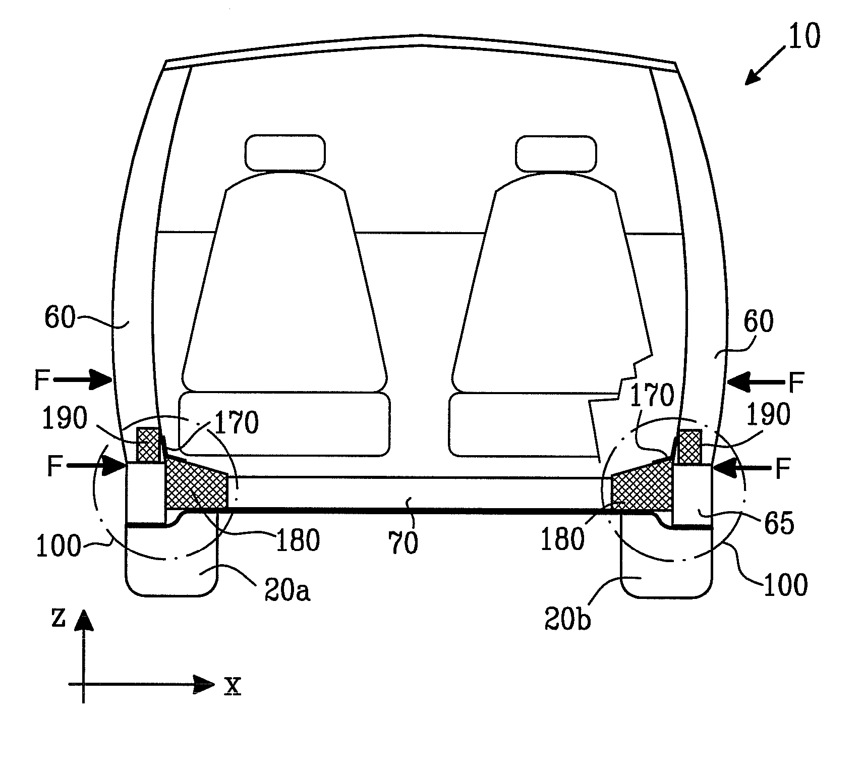
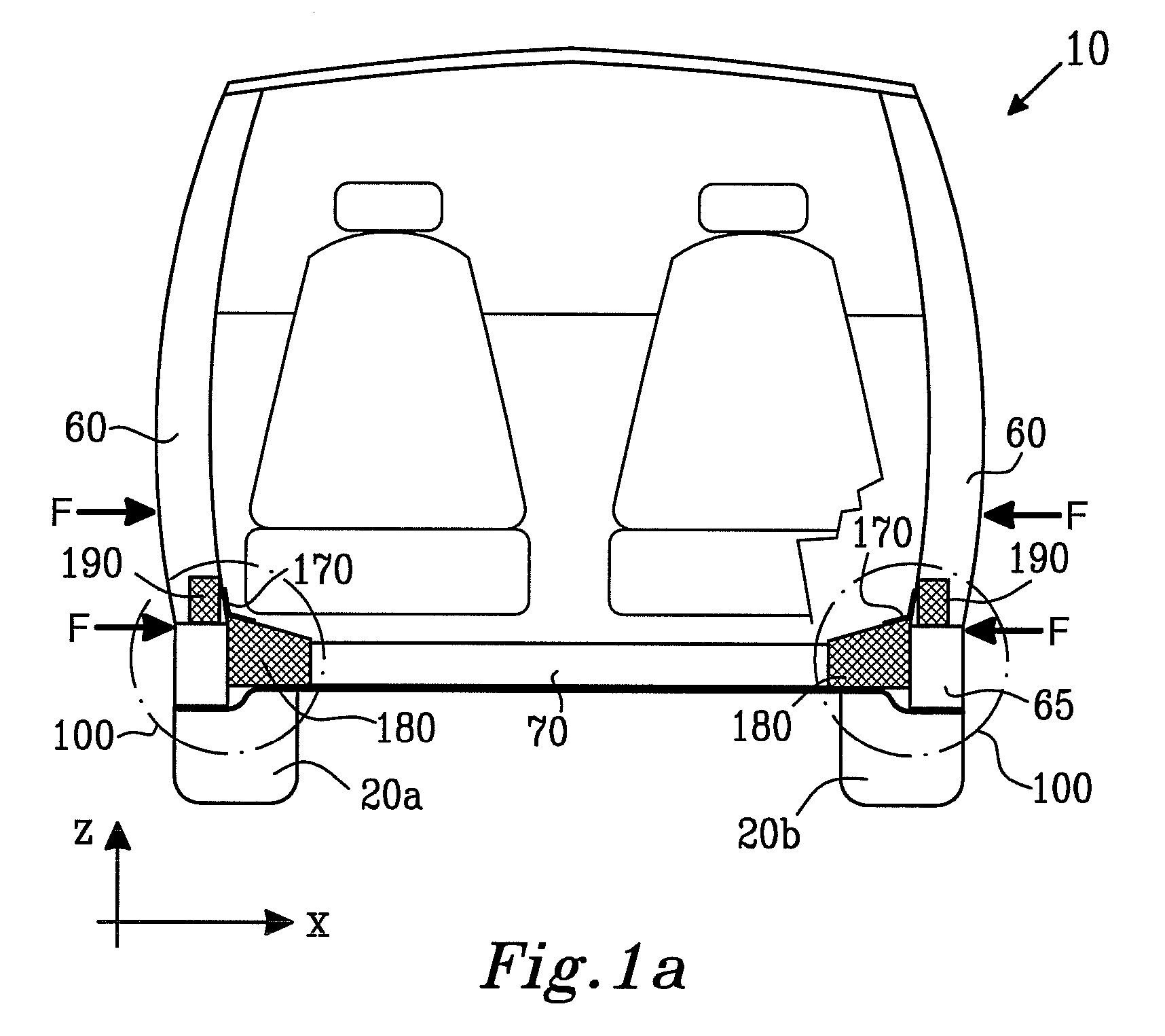
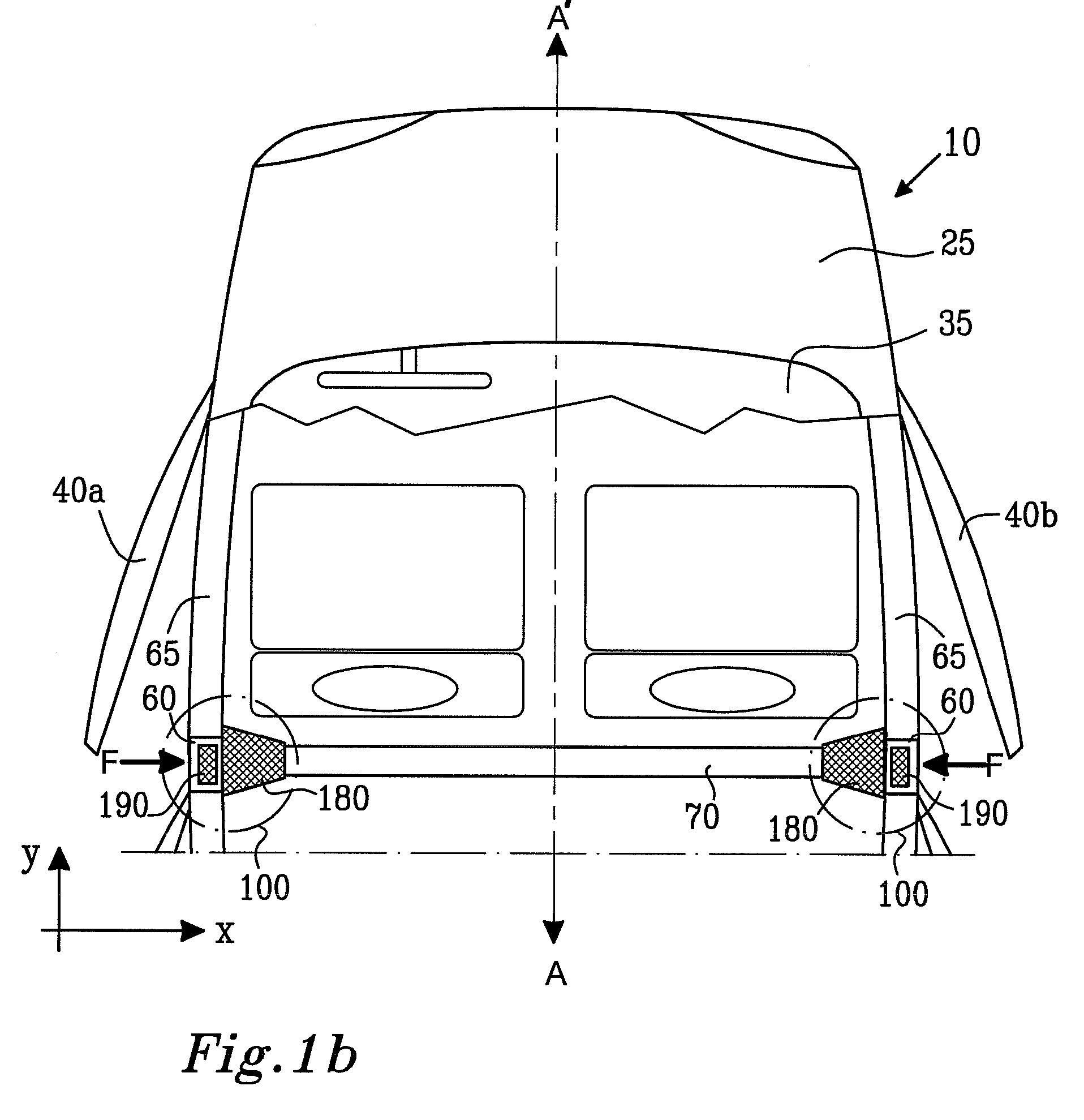
[0035]In order to provide contemporary vehicles with sufficient strength to withstand impacts and crashes at relatively higher vehicle speeds, it is conventional practice in vehicle design to employ strengthening sills and hollow elongate members in vehicle bodies. The hollow elongate members are fabricated from metal sheet which is folded and then welded during manufacture. Such hollow elongate members are not only of relatively lighter weight, but are axially strong and can, in worst case such as a severe crash, provide desirable crumpling characteristics when deformed; such crumpling is capable of absorbing impact kinetic energy. In advanced vehicle design, it is beneficial not only to include elongate strengthening members in an axial direction in a vehicle body, namely substantially aligned from a front end of the body to a rear end thereof, but also in a transverse direction so as to provide the vehicle with improved characteristics for coping with lateral impacts. Such transv...


PUM

PropertyMeasurementUnit
heightaaaaaaaaaa
compressive strengthaaaaaaaaaa

Abstract

There is provided an impact protection structure for providing impact energy absorption at a region substantially between a first transverse strengthening member and a second substantially upright strengthening member of a road vehicle. In operation, the first and second members are disposed substantially mutually perpendicularly. The impact protection structure comprises an energy absorbing block arrangement and a cover arrangement for maintaining the absorbing block arrangement substantially in position during impact. In operation, the impact protection structure is susceptible to reducing lateral damage to the road vehicle in crash or impact situations, thereby potentially increasing passenger and driver safety.

Description

TECHNICAL FIELD[0001]The present invention relates to impact protection structures for road vehicles, for example to lateral impact protection structures. Moreover, the present invention also relates to component parts included in such protection structures. Furthermore, the invention relates to methods of absorbing impact energy in road vehicles provided with such impact protection structures.BACKGROUND OF THE INVENTION[0002]In contemporary road vehicles, for example automobiles, personal safety has become an increasingly important issue to drivers and passengers of such vehicles. Of particular concern regarding safety is damage resulting from frontal vehicle impacts and lateral vehicle impacts. Whereas vehicles can be designed to better cope with frontal impacts, for example by using crumple zones in engine compartments as well as restraining features such as airbags, optimization of vehicles to cope with lateral impacts is technically difficult in that sides of vehicles do not pr...

Claims


Application Information

Patent Timeline
Patent Type & Authority Patents(United States)
IPC IPC(8): B60R19/02
CPCB62D21/157Y10T29/49622
Inventor ROCCATO, MAURIZIOCANATO, PAOLO
Owner VOLVO CAR CORP
Why Eureka
Try Eureka