Wireless controlled light emitting assembly

a technology of light-emitting assembly and wires, which is applied in the field of electronic components and systems, can solve the problems of increasing the physical size and weight of the module, handling problems, and creating additional waste, and disconnection of multiple wires and/or wire assemblies

Inactive Publication Date: 2009-11-10
TE CONNECTIVITY CORP
View PDF13 Cites 37 Cited by
  • Summary
  • Abstract
  • Description
  • Claims
  • Application Information

AI Technical Summary

Benefits of technology

[0003]What is needed is a lightweight light emitting assembly and system requiring less wiring, and is easily and more quickly and efficiently installed, repaired and / or replaced.

Problems solved by technology

This frequently results in interconnection problems, such as bulky, complex, multi-conductor cable assemblies running to each of the LED assemblies or sub-assemblies.
The wired interconnection arrangement increases the required physical size and weight of the module, requiring heavy support structure and poses handling problems during assembly or maintenance.
In addition, a large module having large numbers of LEDs suffers from the drawback that failure of a module or controller requires replacement of the entire module, which is costly and creates additional waste and disconnection of multiple wires and / or wire assemblies.

Method used


Image

  • Wireless controlled light emitting assembly
  • Wireless controlled light emitting assembly
  • Wireless controlled light emitting assembly

Examples


Embodiment Construction

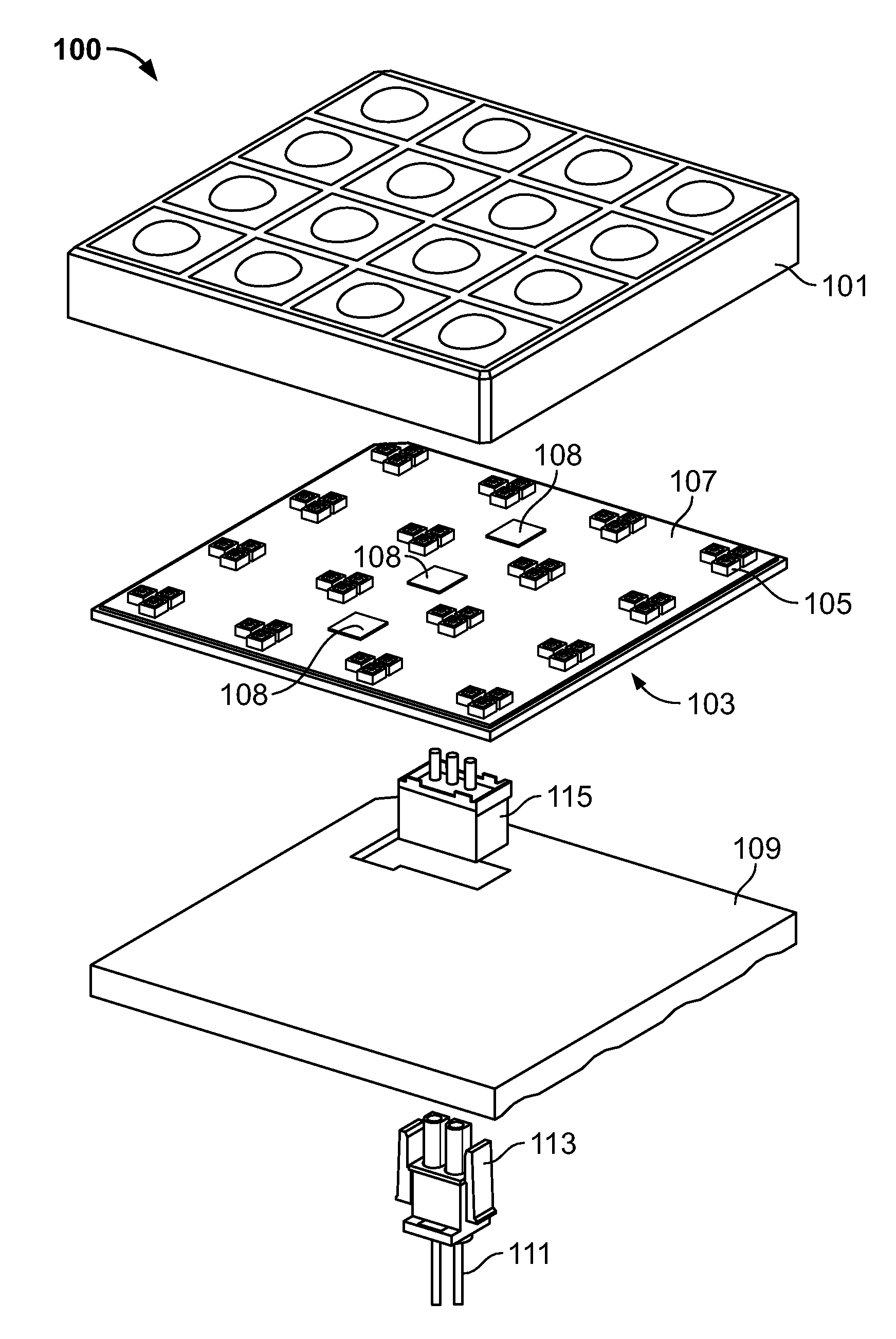
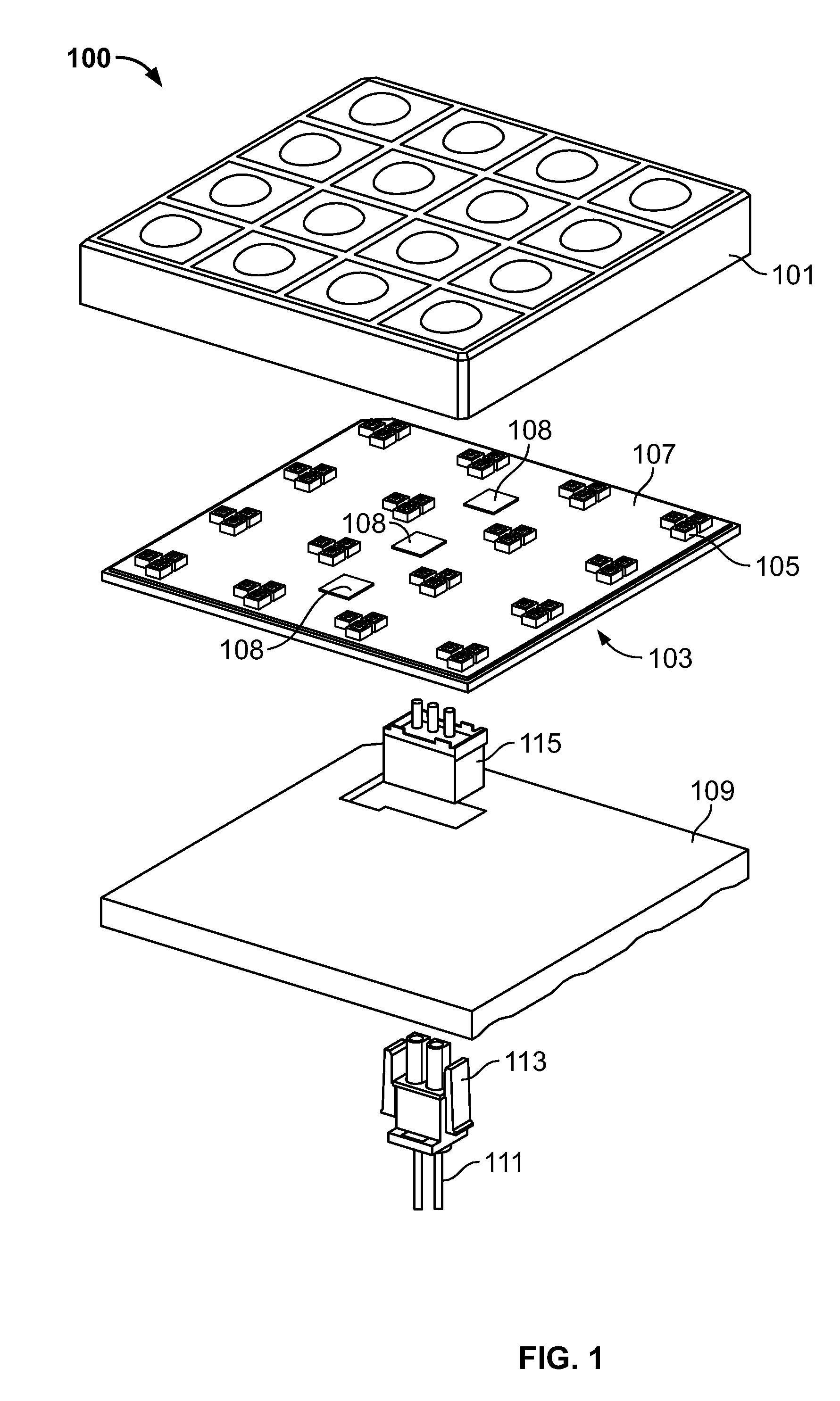
[0019]FIG. 1 shows an exploded view of a light emitting assembly 100 according to an embodiment of the disclosure, having a lens 101 arranged adjacent to a sub-assembly 103 having a plurality of light emitting elements 105. The lens 101 is an optional component that may be arranged adjacent to the light emitting elements 105 to enhance the optical characteristics of the light emitting elements 105 and / or to provide protection for the elements. For example, lens 101 may include a secondary lens array for enhanced optical properties and / or the lens may include a mechanical arrangement, such as louvers, grating or transparent covers for protection of the elements. The sub-assembly 103 includes a plurality of light emitting elements 105 mounted on a surface 107. The light emitting elements 105 may be any light emitting elements 105 known in the art for providing illumination, such as, but not limited to light emitting diodes (LEDs), laser diodes, organic light emitting diodes (OLEDs), i...


PUM


Abstract

A light emitting assembly and a system utilizing a plurality of light emitting assemblies having a plurality of light emitting elements arranged and disposed within a sub-assembly. The assembly also includes a controller in communication with the elements, the controller being capable of receiving wireless signals and / or transmitting wireless signals, the controller also being capable of driving the elements to emit light in response to the wireless signals. The assembly further includes a power source arranged and disposed to provide electrical power to the light emitting elements. A method for providing a light emitting element display is also disclosed.

Description

FIELD OF THE INVENTION[0001]The present invention is directed to electronic components and systems. In particular, the invention is directed to light emitting components and systems.BACKGROUND[0002]The use of LEDs for general-purpose illumination, and in specialty lighting applications such as architectural and video display applications, has increased in recent years. Typically, manufacturers of LED lighting assemblies and design assemblies customize them for the specific LED devices that are used in the illumination displays. The electrical interconnections of the assemblies are often treated as secondary issues, and dealt with separately from the mechanical and aesthetic aspects of the lighting fixture. This frequently results in interconnection problems, such as bulky, complex, multi-conductor cable assemblies running to each of the LED assemblies or sub-assemblies. The wired interconnection arrangement increases the required physical size and weight of the module, requiring hea...

Claims


Application Information

Patent Timeline
Patent Type & Authority Patents(United States)
IPC IPC(8): B60Q3/04H05B44/00
CPCG09F9/33G09F13/22H05B37/0272H05B33/0842H05B33/0896H05B33/0803H05B45/60H05B47/19Y02B20/30H05B45/30
Inventor MCKECHNIE, KEITH J.DAILY, CHRISTOPHER GEORGEWEBER, RONALD MARTIN
Owner TE CONNECTIVITY CORP
Why Eureka
Try Eureka