
Using a triangular waveform to synchronize the operation of an electronic circuit

a technology of electronic circuits and triangular waves, applied in the direction of synchronizing signal speed/phase control, pulse techniques, instruments, etc., can solve the problems of increasing the complexity and cost of controllers ic or inverter control circuits, and achieve the effect of reducing the number of pins and saving wafer spa

Inactive Publication Date: 2010-12-14
MICROSEMI CORP
View PDF18 Cites 3 Cited by
  • Summary
  • Abstract
  • Description
  • Claims
  • Application Information

AI Technical Summary

Benefits of technology

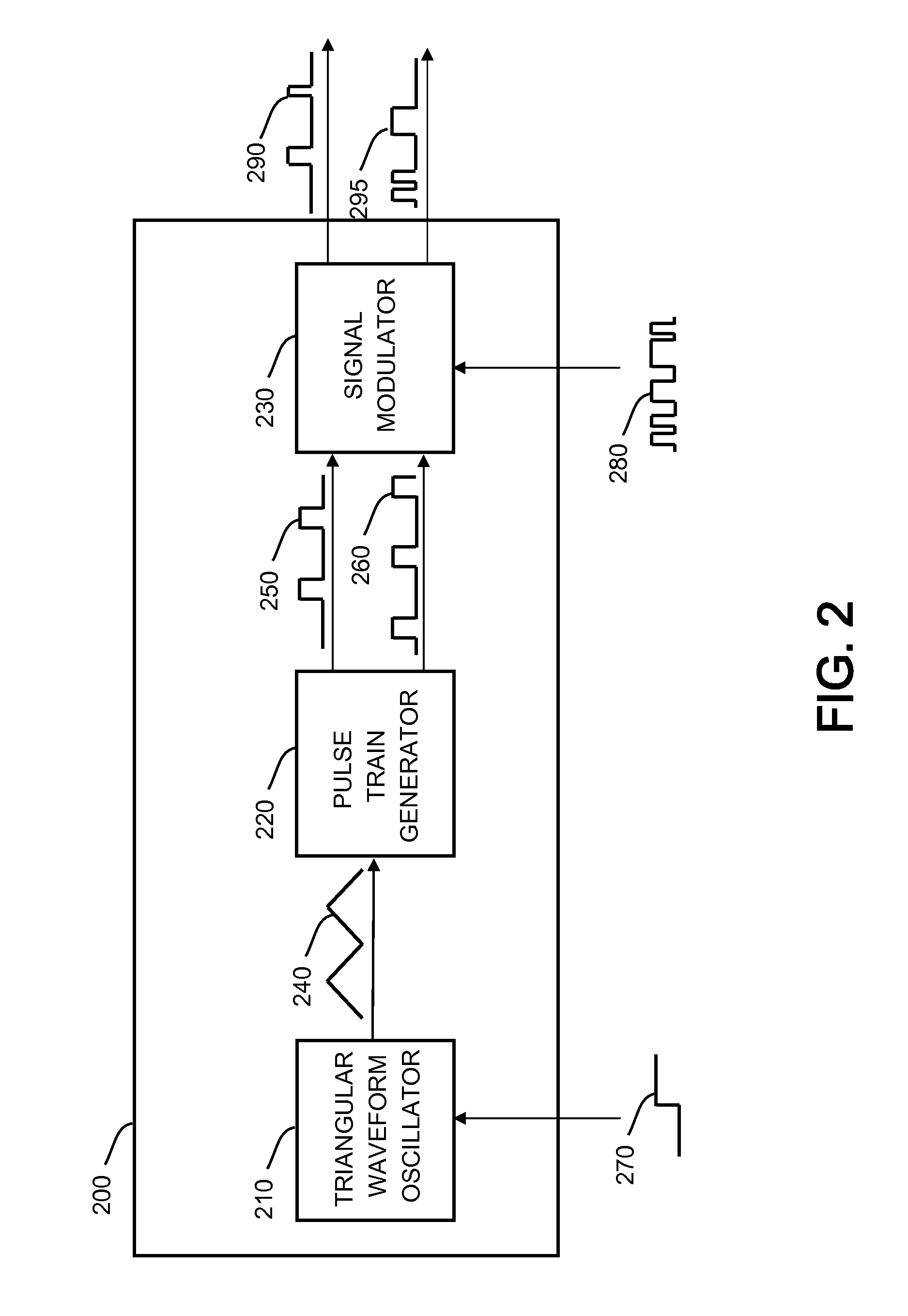
"The present invention provides a method and system for synchronizing electronic circuits with an external synchronizing signal. This is achieved by using a triangular waveform generator initiated by the external synchronizing signal and generating a plurality of pulse trains with a non-zero phase difference between them. The pulse trains are then synchronized with the external synchronizing signal using a PWM signal. This method reduces the need for wiring and saves wafer space, making it suitable for use in CCFL implementation."

Problems solved by technology

These additional circuitry and pins will inevitably increase the complexity and cost of the controller IC or the inverter control circuit.

Method used


Image

  • Using a triangular waveform to synchronize the operation of an electronic circuit
  • Using a triangular waveform to synchronize the operation of an electronic circuit
  • Using a triangular waveform to synchronize the operation of an electronic circuit

Examples


Embodiment Construction

[0020]In the following detailed description, numerous specific details are set forth in order to provide a thorough understanding of the disclosure. However, it will be understood by those skilled in the art that the teachings of the present disclosure may be practiced without these specific details. In other instances, well-known methods, procedures, components and circuits have not been described in detail so as not to obscure the teachings of the present disclosure.

[0021]According to some embodiments, the synchronization method may be incorporated into a CCFL controller. This implementation may be particularly effective for the TV market as well as monitors and thin displays.

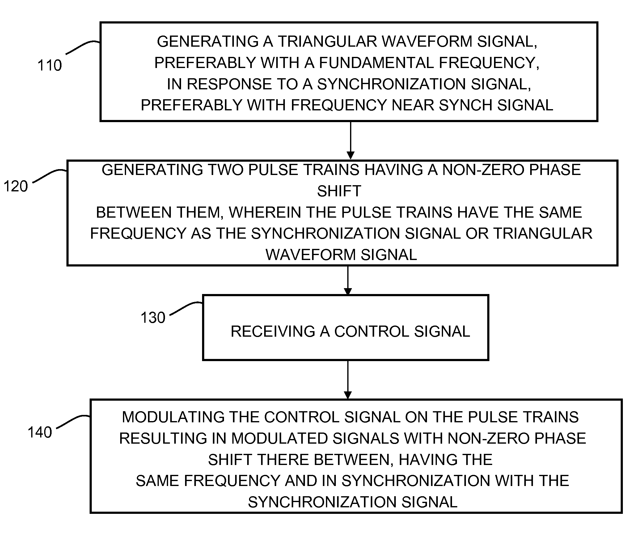
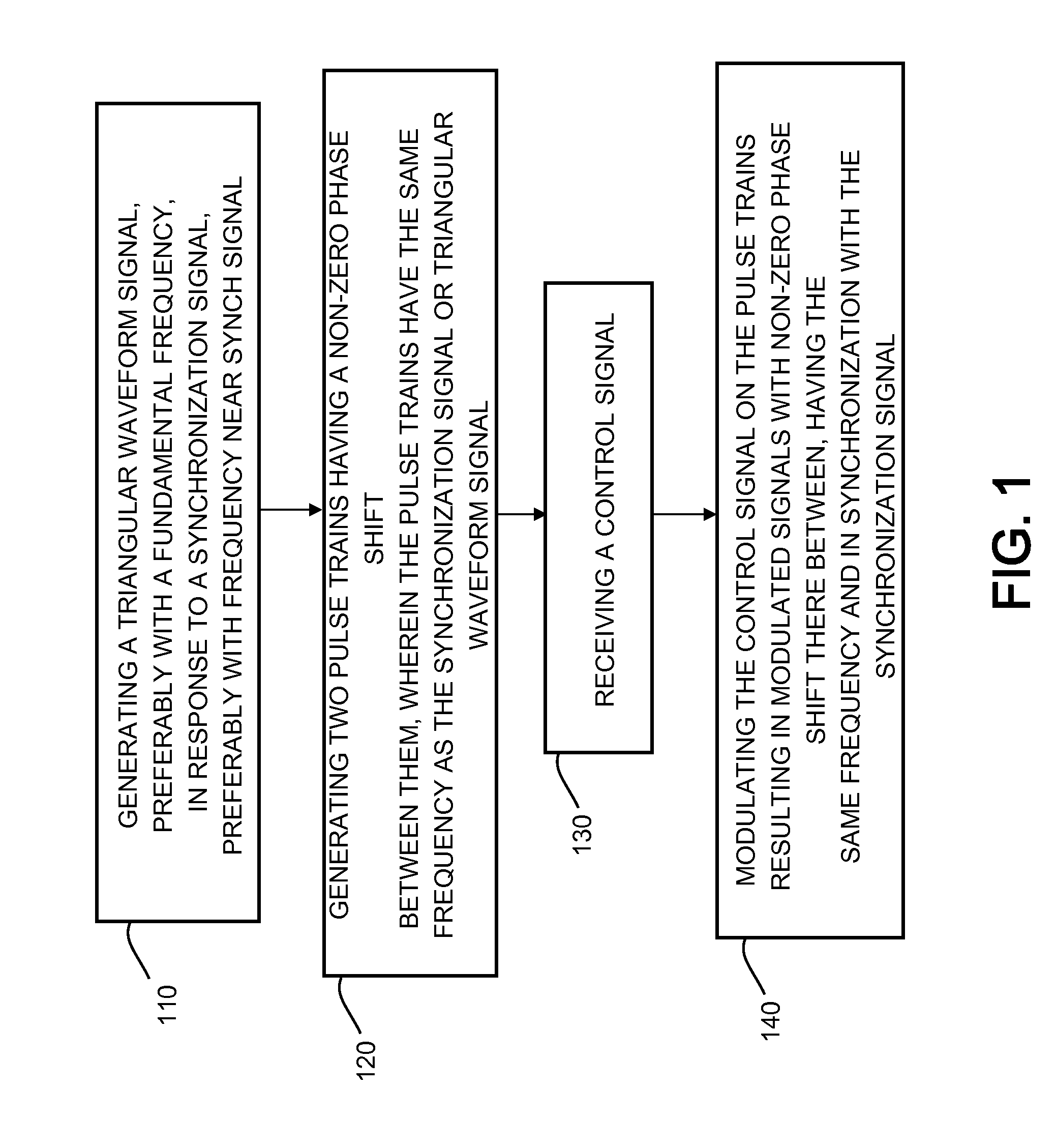
[0022]FIG. 1 is a flowchart showing the stages of the method according to some embodiments of the disclosure. Stage 110 is generating a triangular waveform signal in response to a synchronization signal, which preferably exhibits a periodic frequency. The triangular waveform signal preferably exhibits a funda...


PUM


Abstract

An electronic circuit exhibiting synchronization with an external synchronization signal, the electronic circuit comprising: an input connection arranged to receive a synchronization input signal; a triangular waveform oscillator operatively associated with the synchronization signal input connection and responsive to a condition of the received synchronization input signal to initiate a triangular waveform; and a pulse train generator operatively associated with the triangular waveform oscillator, the pulse train generator arranged to generate a plurality of pulse trains having a fixed non-zero phase relationship between them and a frequency responsive to the condition of the synchronization input signal.

Description

TECHNICAL FIELD[0001]The present invention relates to synchronization of disparate electronic circuits, and more particularly, to synchronization of a plurality of phased signals to an external synchronization input.BACKGROUND OF THE INVENTION[0002]Cold Cathode Fluorescent Lamps (CCFL) are extensively used today as backlights for computer liquid crystal displays (LCD) and LCD televisions. CCFL lamps are typically driven in a push pull configuration such that current flows alternatively in each direction to ensure long life and uniform operation. A CCFL driver thus must provide a pair of complementary drive signals which are out of phase with each other. Typically, a CCFL driver requires a pair of driving signals which are 180° out of phase with each other, however this is not meant to be limiting in any way and 90° phase difference is also required in some particular applications.[0003]Systems that use a plurality of CCFL lamps for a single display require synchronization between th...

Claims


Application Information

Patent Timeline
Patent Type & Authority Patents(United States)
IPC IPC(8): H05B37/02
CPCG09G5/18H03K4/502G09G3/3406
Inventor JIN, XIAOPING
Owner MICROSEMI CORP
Learn More