
Device and methods for use of a dynamic cone penetrometer for evaluating soil compaction

a penetrometer and dynamic cone technology, applied in the direction of mechanical measuring arrangements, instruments, using mechanical means, etc., can solve the problems of cumbersome and fragile existing automated approaches, inability to effectively display the collected data in real-time or transmit data by wireless transmitters, and inability to readily transmit data collected by dcp to remote data-logging and display devices

Active Publication Date: 2009-11-17
SANDY GOLGART SALES
View PDF26 Cites 18 Cited by
  • Summary
  • Abstract
  • Description
  • Claims
  • Application Information

AI Technical Summary

Benefits of technology

The automated system reduces user error, provides accurate and reliable soil compaction data, and enables secure, permanent record-keeping, allowing for real-time evaluation and comprehensive data analysis, even in small openings.

Problems solved by technology

If the required blowcount is reached before the standard penetration is reached, this automatically means a passing condition, and further blows are unnecessary, and not usually pursued.
These presently known automated approaches however are generally cumbersome and fragile and further lack the ability to readily transmit data collected by the DCP to remote data-logging and display devices, such as portable computers or personal digital assistants (“PDAs”) for secure logging and retention of data.
Existing automated approaches are also generally unable to effectively display the collected data in real-time or transmit the data by means of wireless transmitters.
Another difficulty in determining soil compaction (and / or other soil properties) is posed by the smaller openings, such as keyhole openings, that have begun to be used by utility companies, and others, in operations that require installation or repair of underground equipment or settings.
The DCPs of the prior art as presently configured cannot be used for this purpose as readings are almost impossible to be made with any accuracy due to the limited sight lines available.

Method used


Image

  • Device and methods for use of a dynamic cone penetrometer for evaluating soil compaction
  • Device and methods for use of a dynamic cone penetrometer for evaluating soil compaction
  • Device and methods for use of a dynamic cone penetrometer for evaluating soil compaction

Examples


Embodiment Construction

[0031]While the present invention is susceptible of embodiment in various forms, there is shown in the drawings a number of presently preferred embodiments that are discussed in greater detail hereafter. It should be understood that the present disclosure is to be considered as an exemplification of the present invention, and is not intended to limit the invention to the specific embodiments illustrated. It should be further understood that the title of this section of this application (“Detailed Description of the Invention”) relates to a requirement of the United States Patent Office, and should not be found to limit the subject matter disclosed herein.

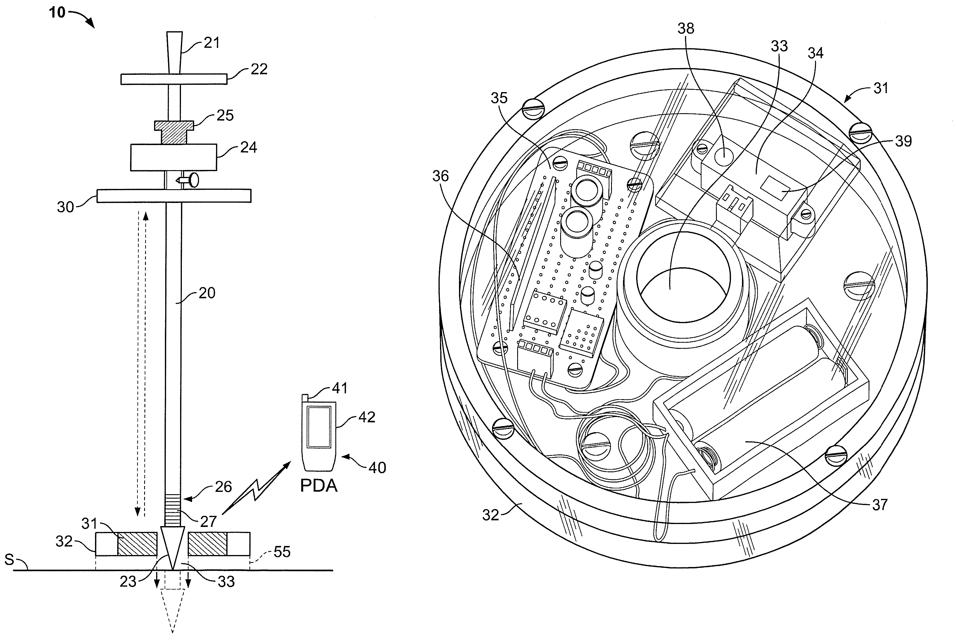
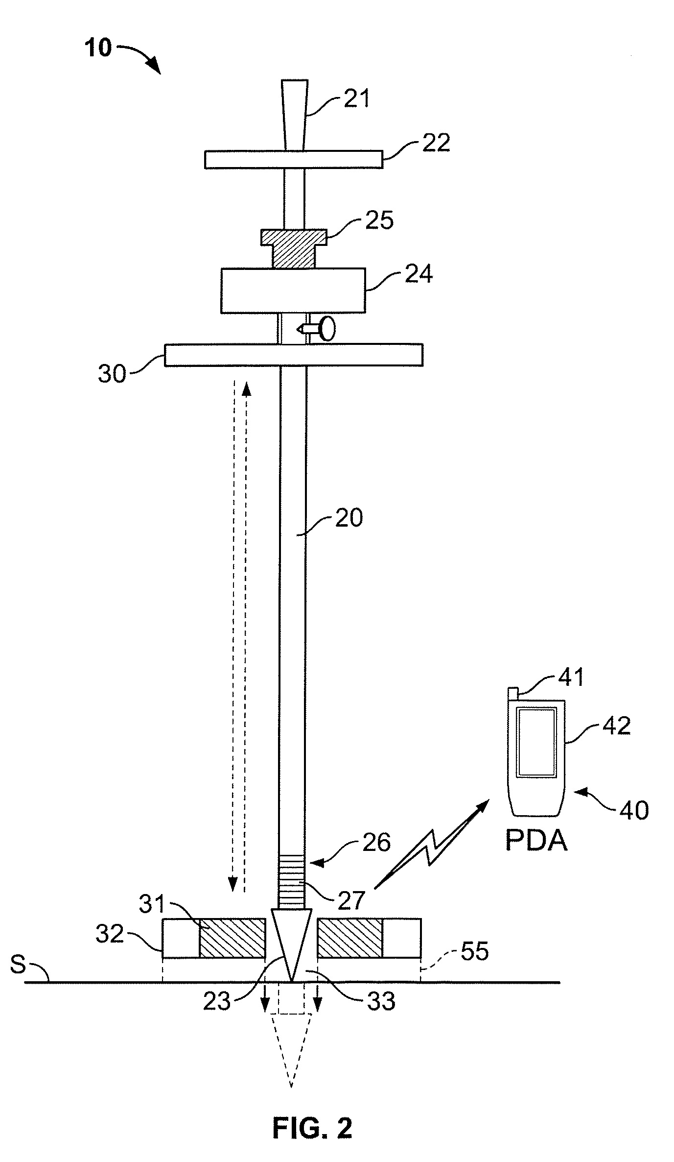
[0032]FIG. 1 shows a dynamic cone penetrometer (“DCP”) 1 having general characteristics in accordance with the teachings of the prior art. Persons having ordinary skill in the art will understand the basic operations of such a device; however, briefly, the tip 2 of the device is generally placed onto the surface of soil “S” whose co...


PUM

PropertyMeasurementUnit
weightaaaaaaaaaa
resistanceaaaaaaaaaa
shear strengthaaaaaaaaaa

Abstract

The present invention includes a device and method for more particularly evaluating the compaction of soil by automating the use of a prior art dynamic cone penetrometer such that user error and error caused by field conditions are eliminated. Recordation of penetrometer data previously not recorded is made more precise by the present invention such that standardized measurement results. The device further includes means for facilitating the determination of compaction of soils through keyhole openings and a means for automating the collection and processing of the generated compaction data.

Description

REFERENCE TO RELATED APPLICATION[0001]This application is related to U.S. Provisional Patent Application Ser. No. 60 / 749,863 filed Dec. 13, 2005 entitled “Automation Of Testing, Recording, And Determination Of Acceptable Status Utilizing A Dynamic Cone Penetrometer (DCP)”, the entirety of which is incorporated as if set forth in its entirety herein.BACKGROUND OF THE INVENTION[0002]Penetrometers and related devices have been used for a variety of geotechnical engineering purposes over the years. Among the well-known types of penetrometers is the utility dynamic cone penetrometer (“DCP”) which is commonly used by utility companies to determine the adequacy and degree of soil compaction in restorations of openings made in roadways or other land features for the purpose of installing or maintaining underground facilities. Other types of DCPs are also presently known to be used in evaluating parameters in addition to soil compaction, including for example resistance to penetration or she...

Claims


Application Information

Patent Timeline
Patent Type & Authority Patents(United States)
IPC IPC(8): G01N3/34
CPCG01N33/24G01N3/48
Inventor KINAST, JOHN ARTHURFARRAG, KHALID A.TODRES, H. A. ALAN
Owner SANDY GOLGART SALES
Learn More