
Shifting gear system and method

a shifting gear and gear system technology, applied in the field of gear systems, can solve the problems of users' difficulty in shifting gears between forward and reverse, and achieve the effects of reducing the amount of force required, facilitating shifting, and reducing the binding force on certain shifting components

Active Publication Date: 2009-11-17
POLARIS IND INC
View PDF23 Cites 21 Cited by
  • Summary
  • Abstract
  • Description
  • Claims
  • Application Information

AI Technical Summary

Benefits of technology

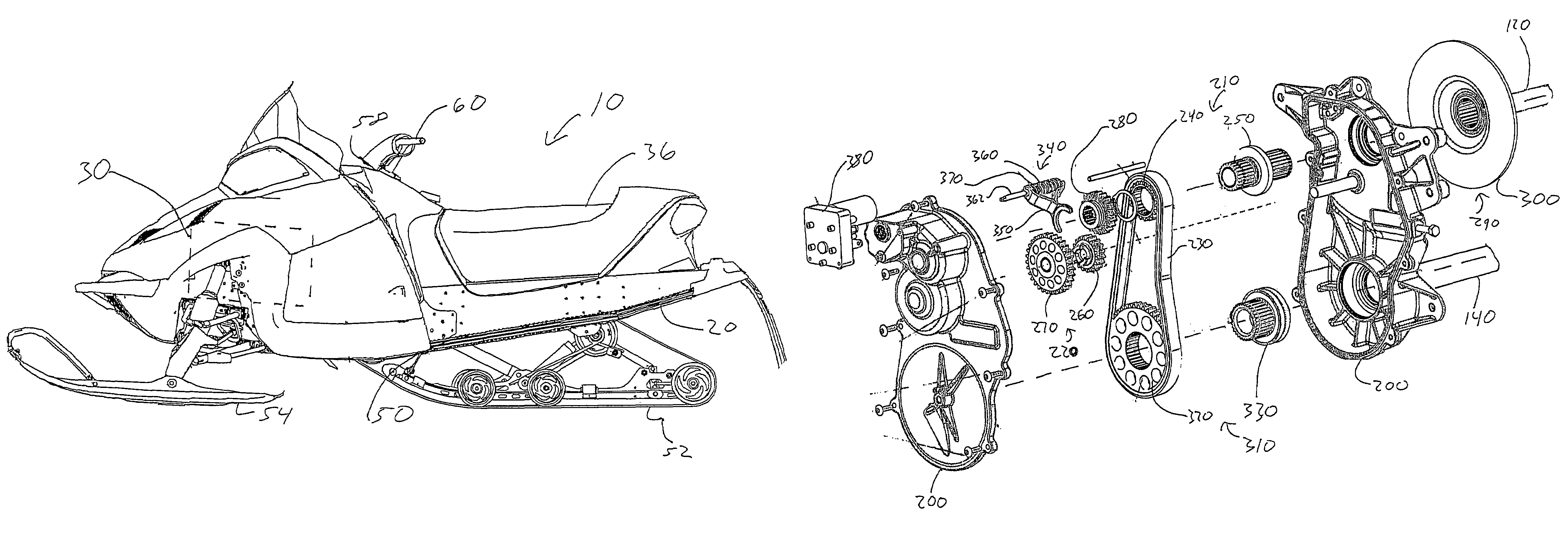
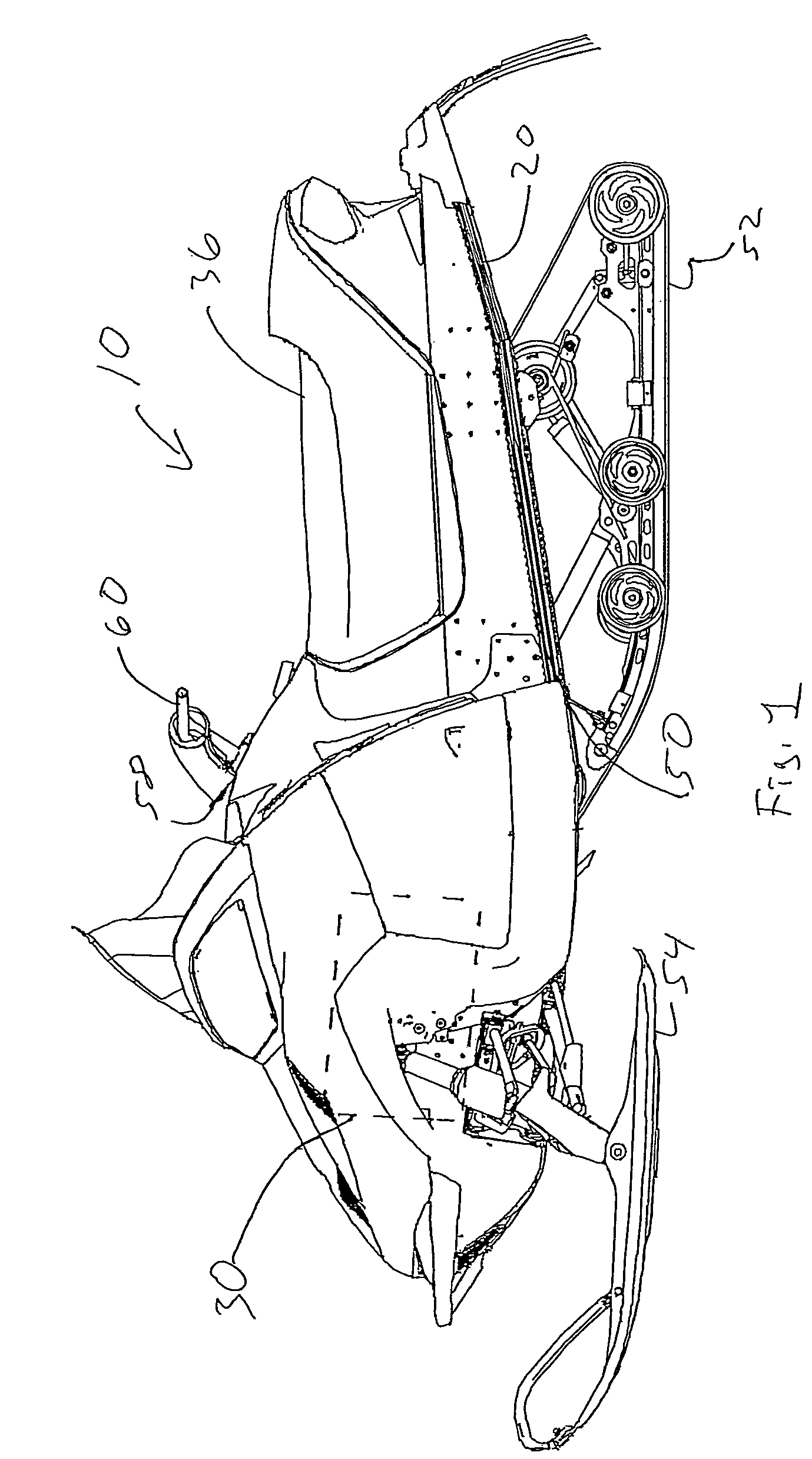
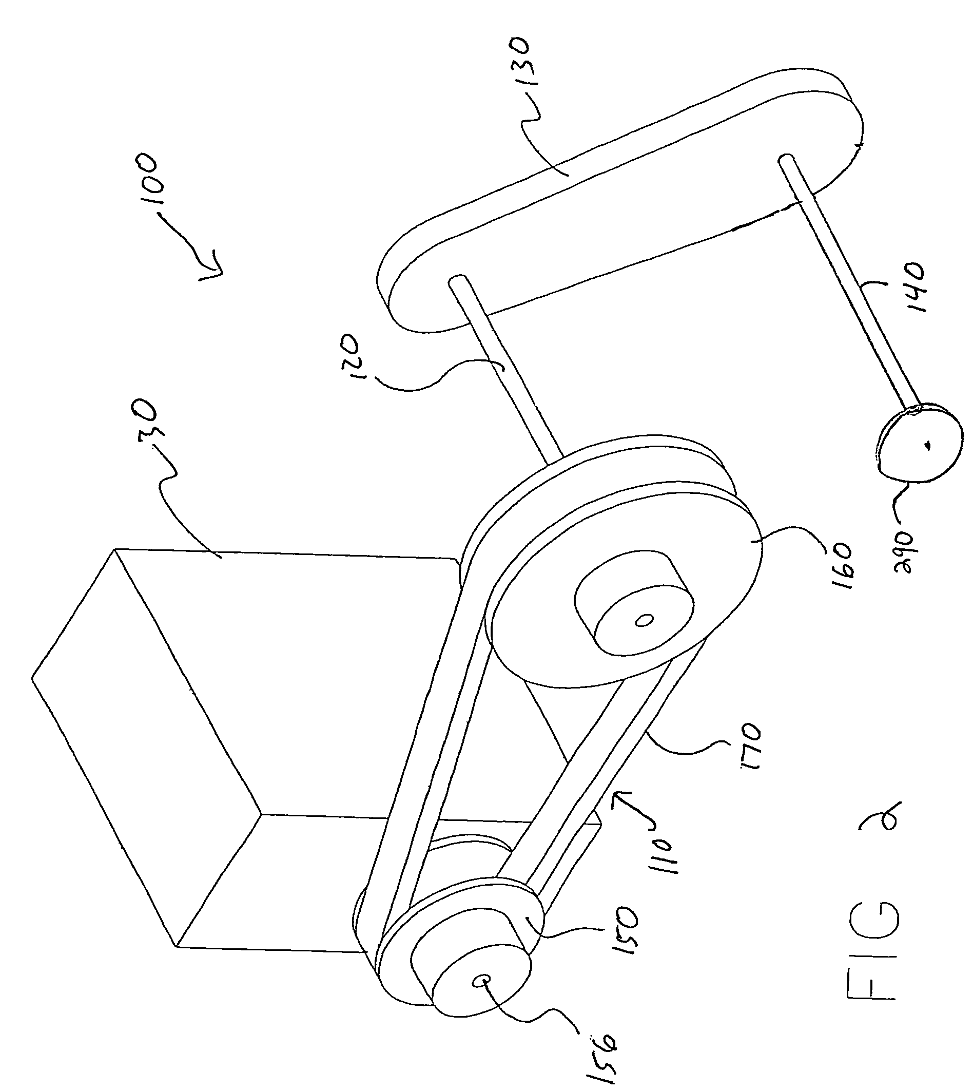
[0004]The various embodiments of the invention facilitate shifting by reducing binding forces on certain shifting components. The reduction of binding forces decreases the amount of force required to complete a shift. In some embodiments, the invention includes a snowmobile comprising a chassis, an engine supported by the chassis, and a drive train operatively connected to the engine. The drive train may comprise a reverse sprocket assembly functionally coupled to an upper sprocket assembly, a jackshaft freely rotatable within the upper sprocket assembly, and a pinion operatively connected to the jackshaft. The pinion may be selectively positionable axially along the jackshaft to a first position that engages the upper sprocket assembly to translate the snowmobile in a forward direction or to a second position that engages the reverse sprocket assembly to translate the snowmobile in a reverse direction. Such a system may substantially isolate the shifting components from binding forces produced between the drive track and braking assembly, thereby allowing for easier shifting between forward and reverse positions. Embodiments of the invention also include a method of shifting between forward and reverse directions.

Problems solved by technology

These binding forces make it difficult for users to shift the gears between forward and reverse, particularly when the vehicle is at an incline or decline.

Method used


Image

  • Shifting gear system and method
  • Shifting gear system and method
  • Shifting gear system and method

Examples


example 1

[0037]In this example, a computer simulation was run to determine the force load applied to the jackshaft in a traditional gear case and an embodiment of the invention for a relatively heavy system. The test parameters for a relatively heavy system are shown in Table 1, the results for a traditional system are shown in Table 2, and the results for an embodiment of the invention are shown in Table 3.

[0038]

TABLE 1Test ParametersWeight of Machine and Rider750lbsEfficiency of Track0.57Diameter of Drive Sprocket0.6525ftDiameter of Lower Sprocket0.427725ftDiameter of Upper Sprocket0.24868ft

[0039]

TABLE 2Forces from an Inclined Slope in Traditional Gear CaseIncline ofLbsFt-lbsLbsFt-lbsPlane inTrackDrive SprocketChainUpper Sprocket toDegreesForceTorqueForceJackshaft Torque1074.2324.22113.2514.0820146.2147.70223.0527.7330213.7569.74326.0840.5440274.7989.65419.2052.1250327.48106.84499.5862.12

[0040]

TABLE 3Forces from an Inclined Slope in an Embodiment of the InventionIncline ofLbsFt-lbsLbsFt-lb...

example 2

[0042]In this example, a computer simulation was run to determine the force load applied to the jackshaft in a traditional gear case and an embodiment of the invention for a relatively light system. The test parameters for a relatively light system are shown in Table 4, the results for a traditional system are shown in Table 5, and the results for an embodiment of the invention are shown in Table 6.

[0043]

TABLE 4Test ParametersWeight of Machine and Rider500lbsEfficiency of Track0.57Diameter of Drive Sprocket0.6525ftDiameter of Lower Sprocket0.427725ftDiameter of Upper Sprocket0.24868ft

[0044]

TABLE 5Forces from an Inclined Slope in Traditional Gear CaseIncline ofLbsFt-lbsLbsFt-lbsPlane inTrackDrive SprocketChainUpper Sprocket toDegreesForceTorqueForceJackshaft Torque1049.4916.1575.509.392097.4831.80148.7018.4930142.5046.49217.3927.0340183.1959.77279.4734.7550218.3271.23333.0541.41

[0045]

TABLE 6Forces from an Inclined Slope in an Embodiment of the InventionIncline ofLbsFt-lbsLbsFt-lbsPla...


PUM


Abstract

Embodiments of the invention facilitate shifting by reducing forces on certain shifting components and includes a snowmobile comprising a chassis, an engine supported by the chassis, a drive train operatively connected to the engine, the drive train comprising a reverse sprocket assembly functionally coupled to an upper sprocket assembly, a jackshaft rotatable within the upper sprocket assembly, and a pinion operatively connected to the jackshaft and selectively positionable axially along the jackshaft to a first position that engages the upper sprocket assembly to translate the snowmobile in a forward direction or to a second position that engages the reverse sprocket assembly to translate the snowmobile in a reverse direction.

Description

FIELD OF THE INVENTION[0001]This disclosure relates to the field of gear systems, and, more particularly, to a snowmobile with an improved shifting gear system.BACKGROUND OF THE INVENTION[0002]Straddle seat type vehicles, such as snowmobiles, are operated on a wide variety of terrain. Much of this terrain is frequently not level, with the vehicle being operated on an incline or a decline. During use, large forces are transmitted through a ground engaging element, such as a drive track, through a drive train to a braking system. In a traditional gearing system, these forces are transmitted through the drive train in a way that puts large binding forces on components used for shifting the vehicle between a forward direction and a reverse direction.[0003]These binding forces make it difficult for users to shift the gears between forward and reverse, particularly when the vehicle is at an incline or decline.BRIEF SUMMARY OF THE INVENTION[0004]The various embodiments of the invention fac...

Claims


Application Information

Patent Timeline
Patent Type & Authority Patents(United States)
IPC IPC(8): B62M27/02F16H57/02F16H9/00
CPCB62M27/02F16H37/027Y10T74/192Y10T74/19219Y10T74/2186
Inventor WARNER, TYZINDA, TODD
Owner POLARIS IND INC
Learn More