
Cosmetic dispenser housing and method

a dispenser and dispenser technology, applied in the field of cosmetic dispenser housing and method, can solve the problems of easy exacerbate flow problems, no attempt is made to cure or ameliorate such problems, and the liquid flow fluctuation of the dispenser tends to be reduced

Inactive Publication Date: 2009-11-17
CONOPCO INC D B A UNILEVER
View PDF32 Cites 1 Cited by
  • Summary
  • Abstract
  • Description
  • Claims
  • Application Information

AI Technical Summary

Benefits of technology

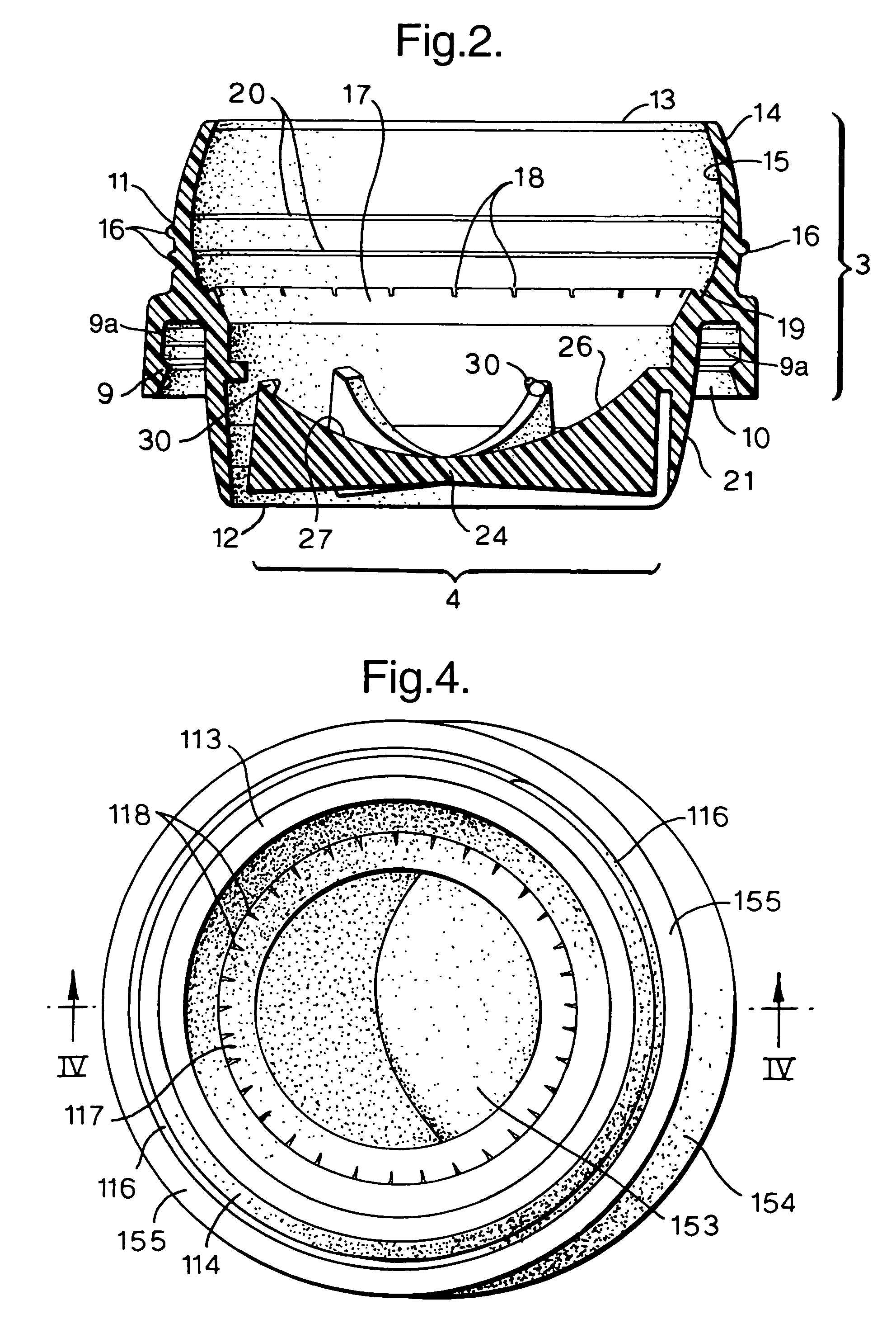
[0014]The present invention is directed to improving the control of the flow of liquid from a roll-on dispenser by modifications to the interior surface of the housing for the roller from its sealing ring through to its outward end, which result in localised disruption of or modification the flow of fluids across that surface in the housing chamber.
[0024]However, it is particularly desirable to employ a spider having a top surface parallel with that of the roller which when the roller is a ball means a convex profile and especially a spider in accordance with the disclosure in a co-pending application of even date entitled “Improvements in a Cosmetic Dispenser”, any supplementary description and accompanying drawings compared with the present text and drawings being incorporated herein by reference. Use of such a particularly desirable spider, that can wipe excess liquid off the ball to leave a film of pre-determined depth, can contribute to the reduction of fluctuations between successive topical applications of the cosmetic formulation.
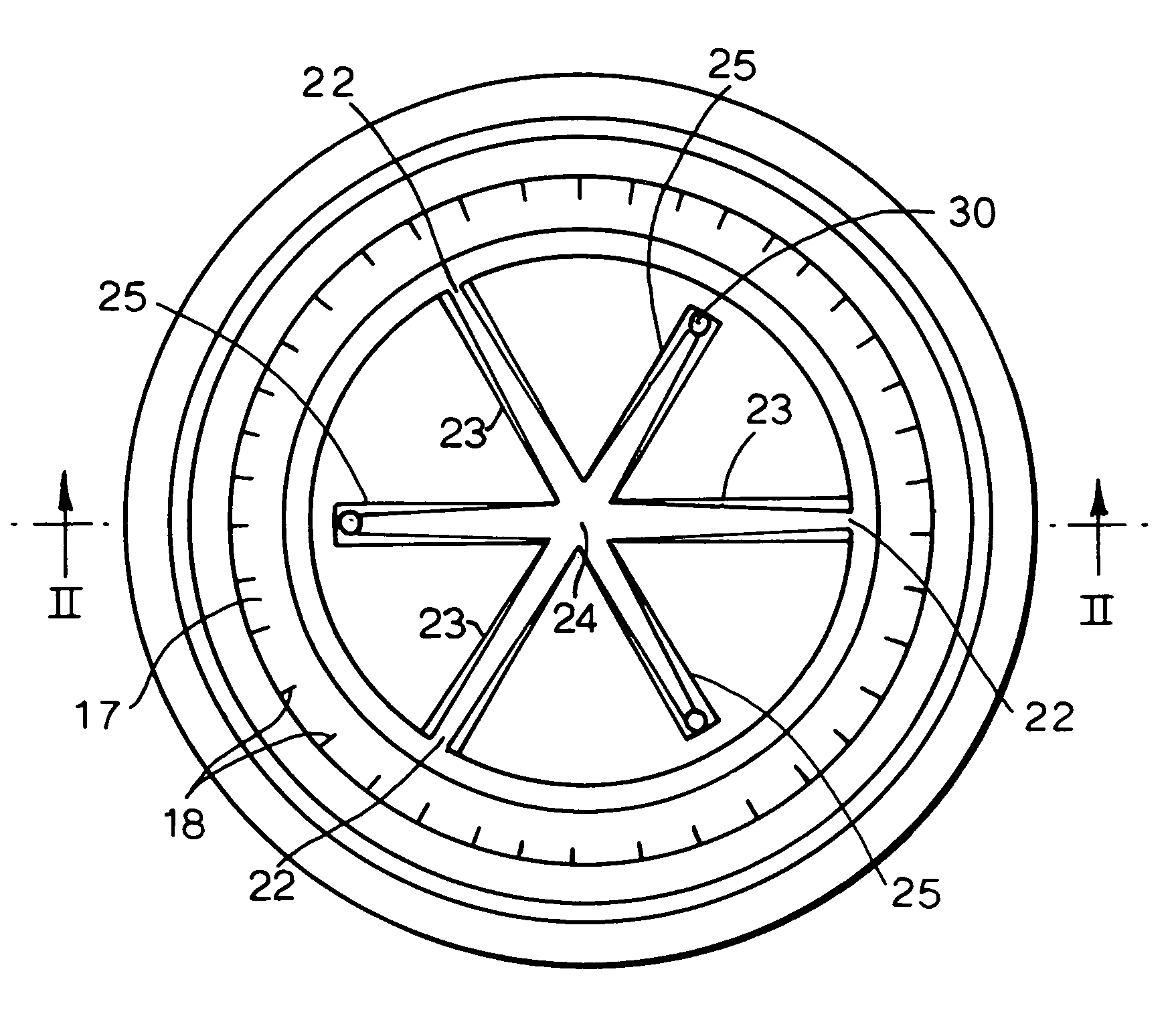
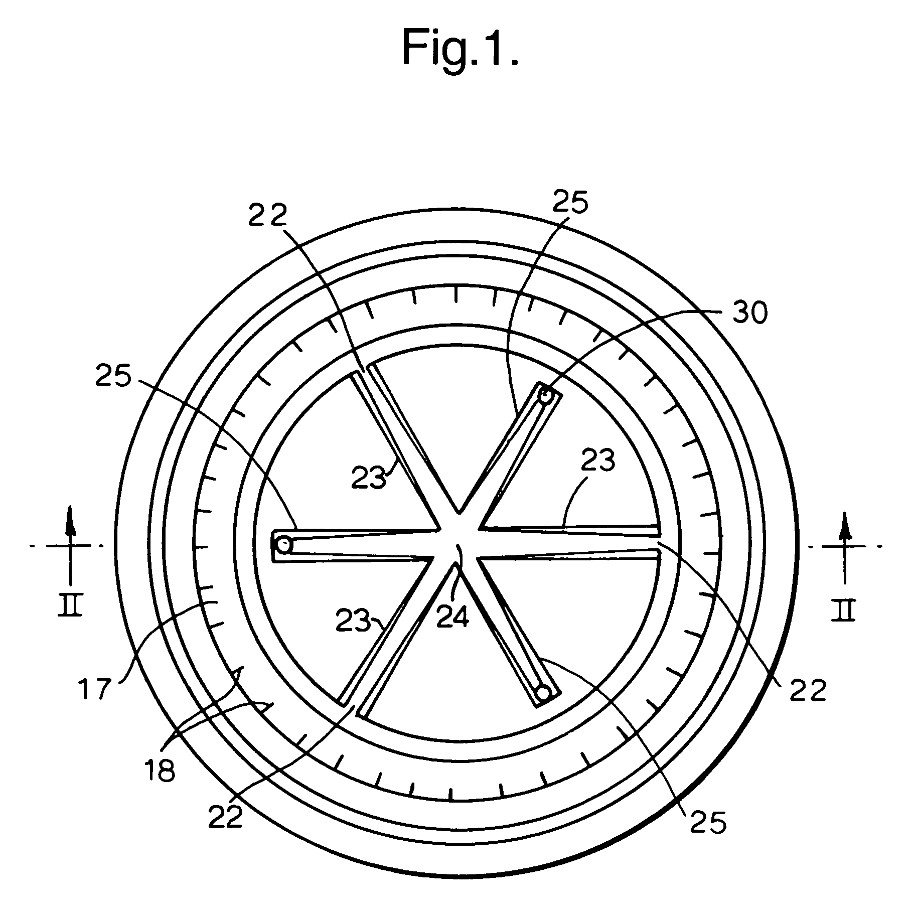
[0027]In many embodiments, the spider comprises a hub from which spokes radiate towards the housing side-wall. If desired, all the spokes can extend between the side-wall and the hub, and for convenience herein these can be called fixed spokes. However, some of the spokes that radiate from the hub and spokes that radiate towards the centre of the housing from the side-wall can have a free end, by which free end is meant that it is not secured to respectively the side-wall or the hub, and for convenience herein these can be called free spokes. It is preferred to employ a mixture of free and fixed spokes, for example in a ratio of from 1:2 to 2:1, and conveniently at 1:1. The free spokes tend to be more flexible whereas the fixed spokes tend to be more rigid and assist in the production of the combined housing and spider, for example in injection moulding. It is especially desirable for fixed and free spokes to arranged symmetrically, such as 1 or 2 free spokes interposed between adjacent fixed spokes. By adopting a symmetrical arrangement, the ball can be centred more easily, thereby ensuring best that the spokes control the depth of liquid film more evenly. One especially desirable arrangement comprises an even number of spokes in total being 4, 6 or 8 having alternate fixed and free spokes symmetrically arranged around the side-wall.
[0029]The localised contact means desirably comprises a boss or pimple standing proud of the surface of the spider, specifically proud of the surface of the spokes facing the ball. The boss or pimple is desirably of round or rounded lateral cross section. The boss or pimple advantageously has a bevelled or rounded chamfer to its contact edge with the ball, thereby to minimise frictional contact with the ball. The boss or pimple advantageously is hemispherical or a cylinder terminating in a hemisphere. The orthogonal height of the pimple, which controls the depth of the liquid film adhering to the ball, is often, for a hand-held cosmetic dispenser, selected in the range of from 300 to 2000 μm and in many instances from 350 to 750 μm.
[0035]Advantageously, the spokes of the spider taper slightly from base to tip. This feature enables the sides of the spoke adjacent to its tip to extend at or close to the radial direction of the ball, for example within about 10 degrees, thereby enabling the tip to encounter the liquid film adhering to the ball approximately orthogonally. The spokes have a surface between their sides, albeit it narrow, which faces the ball surface. Both features assist the spoke to act as a wiper blade. By contrast, if the encounter angle were much less, say between 30 or 60 degrees, providing a corner, its ability to act as a wiper would be compromised.
[0036]In practice, when the dispenser is employed in a conventional manner by users, most conveniently, the spacing between the spider and the ball, for example as defined by the height of the pimple or boss, is less than the spacing between the ball and the housing, even at its tip. That way, the spider controls the depth of fluid adhering to the ball.

Problems solved by technology

One of the problems that has recently been identified comprises an unpredictable fluctuation in the dosage of a liquid by a cosmetic roll-on of conventional size.
However, there is no recognition in U.S. Pat. No. 5,810,495 of the problems of variable fluid flow within the housing variable product dispensation and consequently no attempt is made to cure or ameliorate such problems.
Indeed, the patent discloses the use of a valve inward of the ball housing which could easily exacerbate flow problems.
There is no recognition in such specifications of the problems of air / gas flow within the interior surface of the housing and, consequently, no attempt was made to cure or ameliorate such problems in the specifications.
Indeed, the very presence of an intermediate reservoir with limited inlet area could easily exacerbate flow problems.

Method used


Image

  • Cosmetic dispenser housing and method
  • Cosmetic dispenser housing and method
  • Cosmetic dispenser housing and method

Examples


Embodiment Construction

[0014]The present invention is directed to improving the control of the flow of liquid from a roll-on dispenser by modifications to the interior surface of the housing for the roller from its sealing ring through to its outward end, which result in localised disruption of or modification the flow of fluids across that surface in the housing chamber.

[0015]Herein, the invention is described with particular reference to the roller being a ball, and especially to a spherical ball. However, the skilled person can similarly introduce perturbation into the fluid flow through housings for non-spherical balls or cylindrical rollers, the dimensions and shape of the housing been adapted to accommodate such alternative rollers. References herein to a ball in relation to the instant detailed description and preferred embodiments may accordingly be read to include such alternatives, except where indicated.

[0016]The interior surface of the housing chamber can be modified in a number of different w...


PUM


Abstract

Doses of cosmetic fluid dispensed from a roll-on dispenser can fluctuate significantly between successive applications. This problem can be alleviated by perturbing flow within the roll-on housing, such as air flow, by forming flow perturbators on the interior side-wall of the housing. These perturbators can alternatively or additionally comprise lateral beads or notching an interior sealing ring. The dispenser housing preferably also includes a spider normally located between the roller and the bottle interior, and preferably a resilient spider having an facing surface parallel with the roller that can control the depth of liquid film adhering to the roller, which when the roller is a ball means a concave upper face of similar radius of curvature to that of the ball.

Description

[0001]The present invention relates to a cosmetic dispenser housing and more particularly to improvements to a housing for a ball suitable for attachment to a bottle or reservoir to form a roll-on dispenser for a cosmetic liquid. The invention also relates to a method for smoothing the dosage of a cosmetic liquid from a hand-held cosmetic roll-on dispenser.BACKGROUND TO THE INVENTION[0002]Herein the term fluid indicates a material other than a gas which is capable of flowing without retaining its physical shape and accordingly excludes firm solids which retain their shape when subjected to mild pressure. The term includes liquids or creams which may be aqueous or anhydrous and flowable particulate solids. In particular, the present invention is directed to dispensers of a liquid of low or intermediate viscosity.[0003]One class of dispensers of cosmetic fluids, including in particular deodorants and antiperspirants is commonly called a roll-on dispenser or applicator. In such dispens...

Claims


Application Information

Patent Timeline
Patent Type & Authority Patents(United States)
IPC IPC(8): B43K7/10A45D34/04
CPCA45D34/041
Inventor TAVARES DA SILVA, REGINALDO ALEXANDRE
Owner CONOPCO INC D B A UNILEVER
Learn More