Dock to boat transfer aid for handicapped boaters

a boater and lift technology, applied in the field of lifts for transferring handicapped boaters, can solve the problems of occupying significant space, affecting difficulty or risk for them to go back and forth between docks, and reducing the safety of passengers,

Active Publication Date: 2009-11-17
HANDICAPTAIN BRANDS
View PDF30 Cites 40 Cited by
  • Summary
  • Abstract
  • Description
  • Claims
  • Application Information

AI Technical Summary

Problems solved by technology

Many boaters suffer from physical handicaps that make it difficult or risky for them to go back and forth between a dock and a moored boat on their own, or that require help from others who might themselves be put at risk in helping with the transfer.
Smaller recreational boats and smaller docks typically lack room and support (and sometimes stability) for cranes and ramps.
These use a fairly permanent mounting, take up significant space on the dock, and appear to require other people on the dock to operate the equipment and assist with loading and transfer.
The handicapped boater himself generally seems to remain a passive transferee, which is often unsatisfying and might lead in some cases to giving up the enjoyable pastime of boating.
This system, however, appears to be expensive, complex to install, and suitable only for relatively large boats.
It further requires additional boom and support structure on the boat and / or on the dock in order to transfer the boater between boat and dock, and the transfer would be subject to the rocking of the boat.
None of the foregoing transfer devices is particularly suitable for use in transferring people between small, often seasonal, docks in shallow water and small recreational boats housed in boat lifts.
The extra spacing from the dock created by the lift; the surrounding frame, lift cradle, and canopy structure; and the small, sometimes rickety nature of the dock make the use of traditional boat-side and dockside transfer devices impractical.
The usual alternative is to rely on personal lifting help from family and friends, which can be risky for all involved.

Method used


Image

  • Dock to boat transfer aid for handicapped boaters
  • Dock to boat transfer aid for handicapped boaters
  • Dock to boat transfer aid for handicapped boaters

Examples


Embodiment Construction

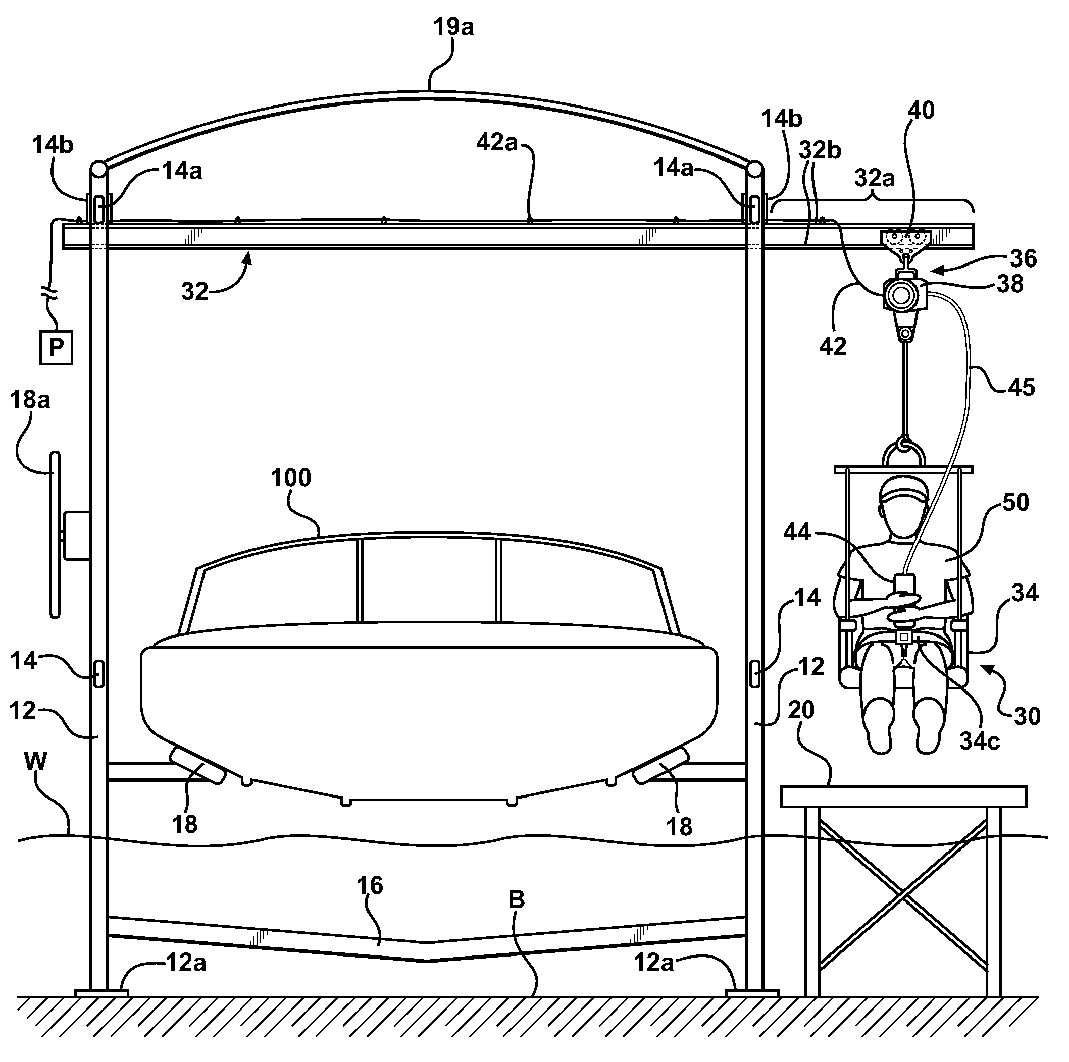
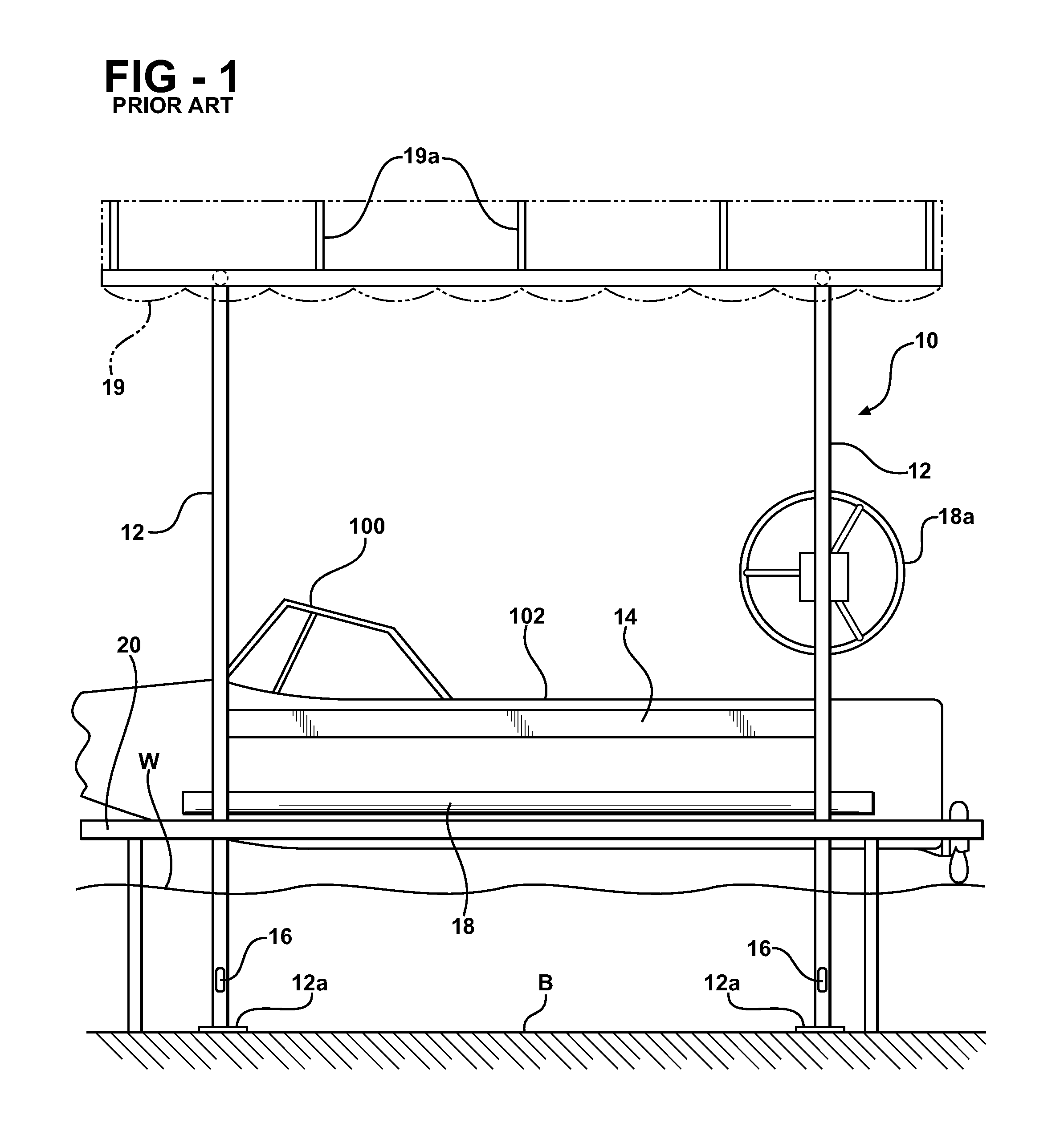
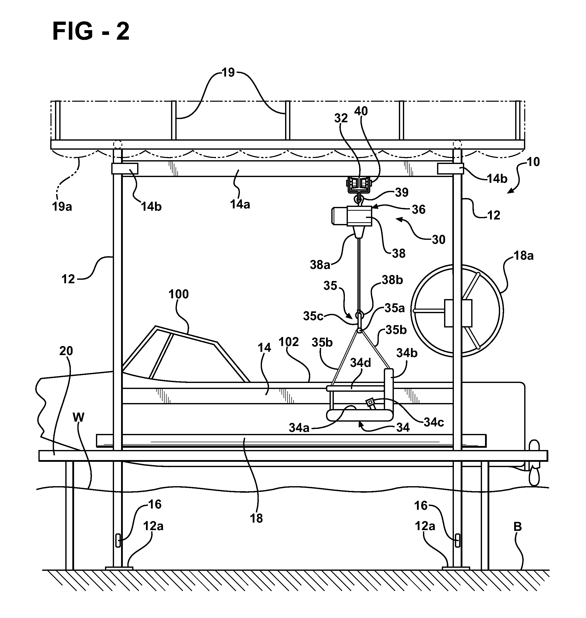
[0024]Referring first to FIG. 1, a conventional boat lift 10 containing a boat 100 is illustrated next to a seasonal (in for spring, out for winter) dock 20. Illustrated boat lift 10 represents a typical seasonal, shallow-water boat lift in somewhat schematic fashion, since many different makes and models of this type of boat lift are known and commercially available and will lend themselves to use with the invention with only minor modification. Boat lift 10 generally includes four or more supporting pipe columns 12 anchored on lake bottom B with feet 12a; side frame members 14 connecting and bracing pipe columns 12 on the long sides of the boat lift; and fore and aft end frame members 16 connecting and bracing pipe columns 12 on the ends of the boat lift, below the waterline W to provide clearance for the boat 100 as it enters and exits the boat lift. End frame members 16 generally have a shallow V-shape or curve to give clearance for the hull of boat 100 when the boat is in the w...


PUM


Abstract

A personal transfer device for transferring a boater from a dock to a boat moored in a boat lift adjacent the dock, and back again. A cantilevered support is secured to an upper part of the boat lift frame, the support's free end extending out over the dock at a height that does not interfere with normal use of the dock. A hoist carriage, for example a monorail trolley hoist, is movably secured on the cantilever support, and is connected to a transport chair that can be located over the dock at a convenient height for a handicapped boater to seat and / or secure himself. A controller is accessible to the boater seated in the transport chair to raise himself off the dock to a height sufficient to clear any intervening boat lift structures or frame members, and to then transport himself horizontally along the support through the boat lift structure to the boat, where he then lowers himself onto the boat using the controller.

Description

FIELD OF THE INVENTION[0001]The invention is in the field of lifts for transferring handicapped boaters between docks and moored boats.BACKGROUND OF THE INVENTION AND DESCRIPTION OF RELATED ART[0002]Many boaters suffer from physical handicaps that make it difficult or risky for them to go back and forth between a dock and a moored boat on their own, or that require help from others who might themselves be put at risk in helping with the transfer.[0003]Ships, loading docks and oilrig platforms are known to use large cargo and personnel transfer capsules and cages, often moved with gantry-type cranes, to transfer people and cargo between a ship and the dock or platform.[0004]Large boats and large permanent docks are often provided with devices such as extendable ramps to help handicapped boaters, especially wheelchair users, to get from the dock to the boat and back again.[0005]Smaller recreational boats and smaller docks typically lack room and support (and sometimes stability) for c...

Claims


Application Information

Patent Timeline
Patent Type & Authority Patents(United States)
IPC IPC(8): B66B9/08
CPCA61G3/063A61G7/1015A61G7/1059A61G7/1065A61G7/1042A61G2200/34Y10S414/134A61G2220/00
Inventor BEGLEY, ADAM
Owner HANDICAPTAIN BRANDS
Why Eureka
Try Eureka