
Systems and methods operable to allow loop powering of networked devices

a networked device and loop powering technology, applied in the direction of power supply for data processing, liquid/fluent solid measurement, instruments, etc., can solve the problems of cumbersome network environment, cumbersome network environment, and inability to contact emergency services via independent power telephones

Active Publication Date: 2009-11-17
KINETIC TECH INT HLDG LP
View PDF5 Cites 14 Cited by
  • Summary
  • Abstract
  • Description
  • Claims
  • Application Information

AI Technical Summary

Benefits of technology

The present invention provides a system and method for providing a voltage power feed to network attached devices (PDs) through differential cable pairs. This system includes a network device with a network connector, a protection circuit, and a switching / rectifying circuit. The network device separates the power signal from the data signal and conducts it to the network PHY module and power management module, which then powers the PD. The invention also provides a method for at least partially powering a network attached PD from a power signal fed through a network connection. The technical effects of the invention include improved surge protection, proper polarity of power signal, and efficient power management for network attached devices.

Problems solved by technology

Additionally, power distributed over a network such as an Ethernet network may provide an uninterruptible power supply (UPS) to key components or devices that normally would require a dedicated UPS.
One drawback of VoIP telephony is that in the event of a power failure, the ability to contact to emergency services via an independently powered telephone is removed.
However, these power distribution schemes within a network environment typically require cumbersome, real estate intensive, magnetic transformers.
Additionally, power over Ethernet (PoE) requirements under 802.3 are quite stringent and often limit the allowable power.
There are many limitations associated with using these magnetic transformers.
This may further limit the performance of the communication channel.
Additionally, failures associated with transformers often account for a significant number of field returns.
The magnetic fields associated with the transformers can result in lower electromagnetic interference (EMI) performance.

Method used


Image

  • Systems and methods operable to allow loop powering of networked devices
  • Systems and methods operable to allow loop powering of networked devices
  • Systems and methods operable to allow loop powering of networked devices

Examples


Embodiment Construction

[0024]Preferred embodiments of the present invention are illustrated in the FIGs., like numerals being used to refer to like and corresponding parts of the various drawings.

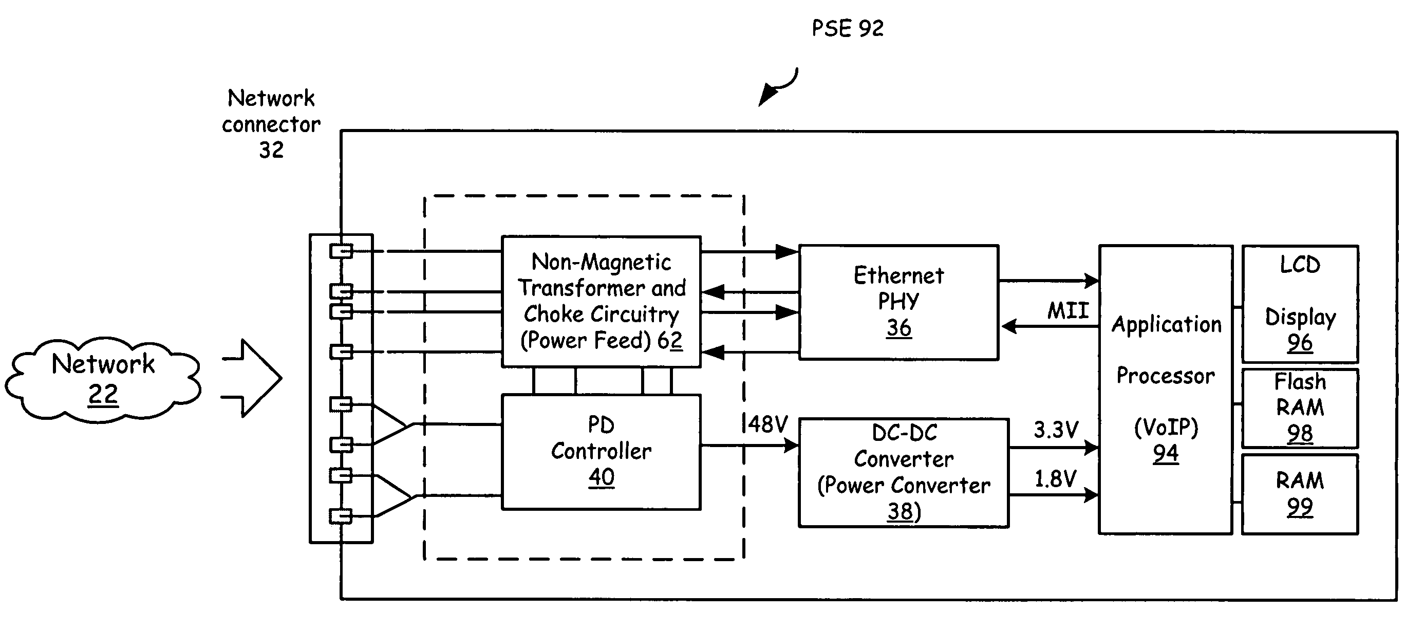
[0025]The 802.3 Ethernet Standards, which is incorporated herein by reference, allow loop powering of remote Ethernet devices (802.3af). The Power over Ethernet (PoE) standard and other like standards intends to standardize the delivery of power over Ethernet network cables in order to have remote client devices powered through the network connection. The side of link that supplies the power is referred to as Powered Supply Equipment (PSE). The side of link that receives the power is referred to as the Powered device (PD).

[0026]Replacing the magnetic transformer of prior systems while maintaining the functionality of the transformer has been subsumed into the embodiments of the present invention. In order to subsume the functionality of the transformer, the circuits provided by embodiments of the present inventio...


PUM


Abstract

Embodiments of the present invention provide a network device operable to receive a network signal that may include both power and data from a coupled network. This network device includes a network connector and an integrated circuit. The network connector physically couples the network device to the network. An optional protection circuit may provide surge protection or incoming network signals received by the network device through the network connector. An optional switching / rectifying circuit sees the output of the protection circuit and is operable to rectify a power signal when contained within the network signal. The integrated circuit further includes a power feed circuit conductively coupled to the protection circuit and the rectifying circuit. This power feed circuit is operable to separate and pass the received data signal to a network physical layer and separate and pass the received power signal to a power management module. The power management module electrically couples to the integrated circuit but is not necessarily part of the integrated circuit. The power management module is operable to at least partially power the network device for specific circuits within the network device from the received power signal.

Description

CROSS REFERENCE TO RELATED APPLICATIONS[0001]This application claims the benefit of priority to and incorporates herein by reference in its entirety for all purposes, U.S. Provisional Patent Application No. 60 / 665,766 entitled “SYSTEMS AND METHODS OPERABLE TO ALLOW LOOP POWERING OF NETWORKED DEVICES,” by John R. Camagna, et al. filed on Mar. 28, 2005. This application is related to and incorporates herein by reference in its entirety for all purposes, U.S. patent application Ser. Nos. 11 / 207,595 entitled “METHOD FOR HIGH VOLTAGE POWER FEED ON DIFFERENTIAL CABLE PAIRS,” by John R. Camagna, et al.; and 11 / 207,602 entitled “A METHOD FOR DYNAMIC INSERTION LOSS CONTROL FOR 10 / 100 / 1000MHZ ETHERNET SIGNALLING,” by John R. Camagna, et al., which have been filed concurrently.TECHNICAL FIELD OF THE INVENTION[0002]The present invention relates generally to power distribution, and more particularly, a solid state transformer-less method for coupling high bandwidth data signals and power signals...

Claims


Application Information

Patent Timeline
Patent Type & Authority Patents(United States)
IPC IPC(8): G06F1/26
CPCG06F1/266
Inventor CAMAGNA, JOHN R.GHOSHAL, SAJOLCREPIN, FRANCOIS
Owner KINETIC TECH INT HLDG LP
Learn More