Removable externally mounted bridge crane for shipping containers

a crane and shipping container technology, applied in the field of self-erecting cranes, can solve the problems of insufficient overhead clearance or capacity of stowage compartments and holds on ships to mount an adequate lifting, take up too much valuable storage space inside, and inconvenient assembly and installation, etc., to achieve the effect of reliably transferring loads, reducing labor intensity, and ensuring safety

Inactive Publication Date: 2009-11-24
USA AS REPRESENTED BY THE SEC OF THE NAVY THE
View PDF13 Cites 14 Cited by
  • Summary
  • Abstract
  • Description
  • Claims
  • Application Information

AI Technical Summary

Benefits of technology

[0008]The present invention provides a readily assembled and installed X-Y bridge crane for lifting and moving loads at the end of a shipping and stowage container having block-shaped corner fittings at top corners and bottom corners at its end. Rotatable top securing brackets engage the top block-shaped corner fittings, and rotatable bottom securing brackets engage the bottom block-shaped corner fittings. A pair of elongate brace members has inner and outer end portions, and the inner end portions are rotatably connected to the rotatable bottom securing brackets. A rectangular framework has inner extensions, outer projecting parts, and a laterally extending hoist-traveling beam. The inner extensions are connected to the top securing brackets and the outer projecting parts of the framework are connected to the outer end portions of the elongate brace members. A hoist is mounted on the hoist-traveling beam for lifting and moving loads on the framework and first and second displacement mechanisms are connected to the hoist to linearly displace it in orthogonal X and Y directions. The framework includes a pair of longitudinal members extending in the X-direction connected to a pair of lateral members extending in the Y-direction. A pair of cable braces are each connected at opposite ends to upward projecting parts at the ends of each of the longitudinal members at the four corners of the framework. The cable braces diagonally extend above and across the framework in a mutually crossing relationship to further strengthen it to bear and transfer loads reliably. Multi-wheeled roller assemblies mounted on opposite ends of the hoist traveling beam support and allow the hoist traveling beam to ride on the upper surfaces of the longitudinal members between the lateral members of the framework. Installation cables extending from a winch at the container are connected to one of the lateral members. Reeling-in the installation cables by the winch raises the brace members, framework, hoist-traveling beam, and hoist above the ground and draws them toward the end of the container during installation of the bridge crane on the container.

Problems solved by technology

When such non-fixed lifting equipments are available on ships at sea, ship motions may make the use of such forklifts or portable hoists impractical and / or unsafe.
In addition, some stowage compartments and holds on ships may have insufficient overhead clearance or capacity to mount an adequate lifting device at the container's ends.
Cranes potentially can be mounted internally in the containers, but these might take up too much valuable storage space inside.
Additionally, such a crane can have a fixed size and may not be removable or further erectable.

Method used


Image

  • Removable externally mounted bridge crane for shipping containers
  • Removable externally mounted bridge crane for shipping containers
  • Removable externally mounted bridge crane for shipping containers

Examples


Embodiment Construction

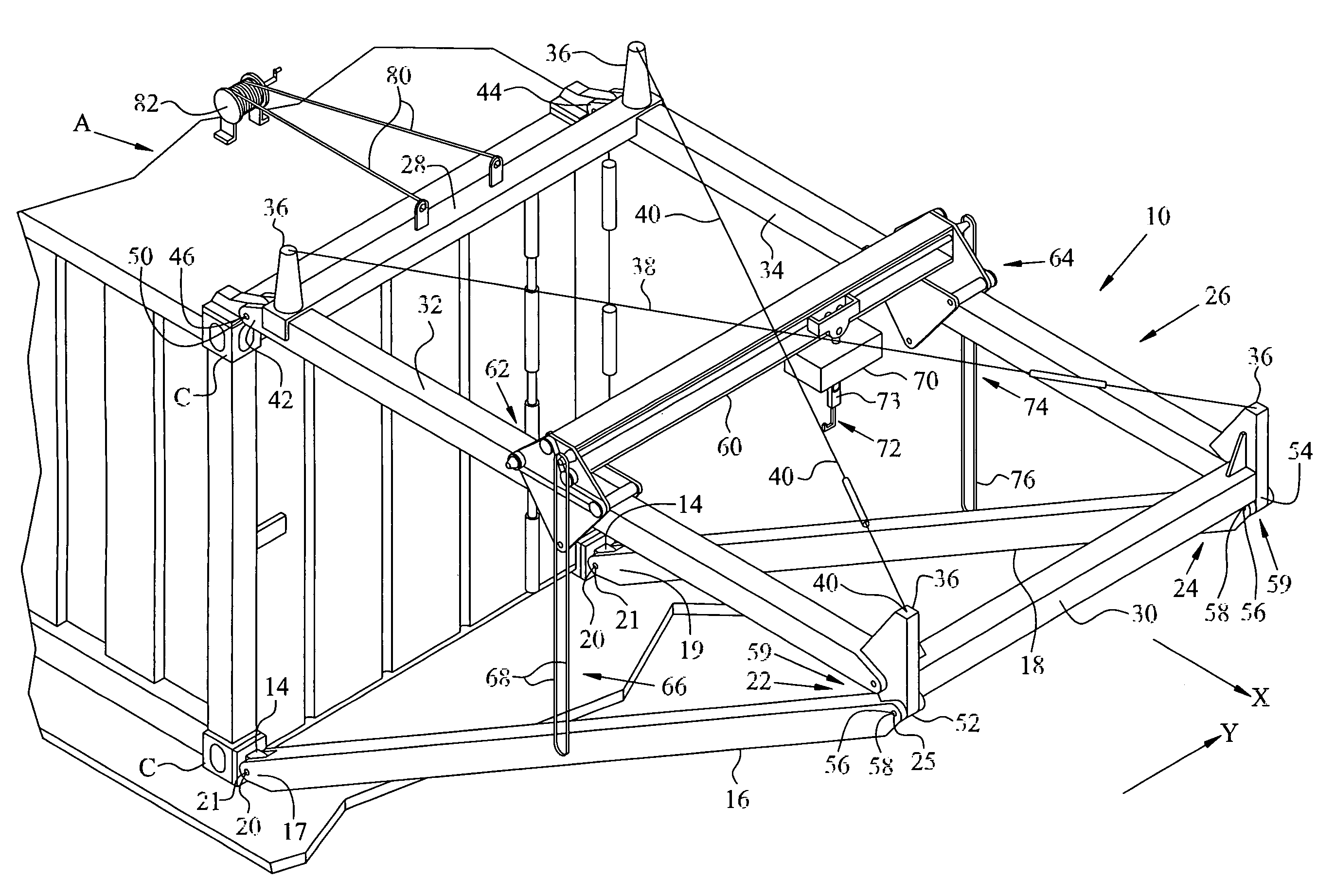
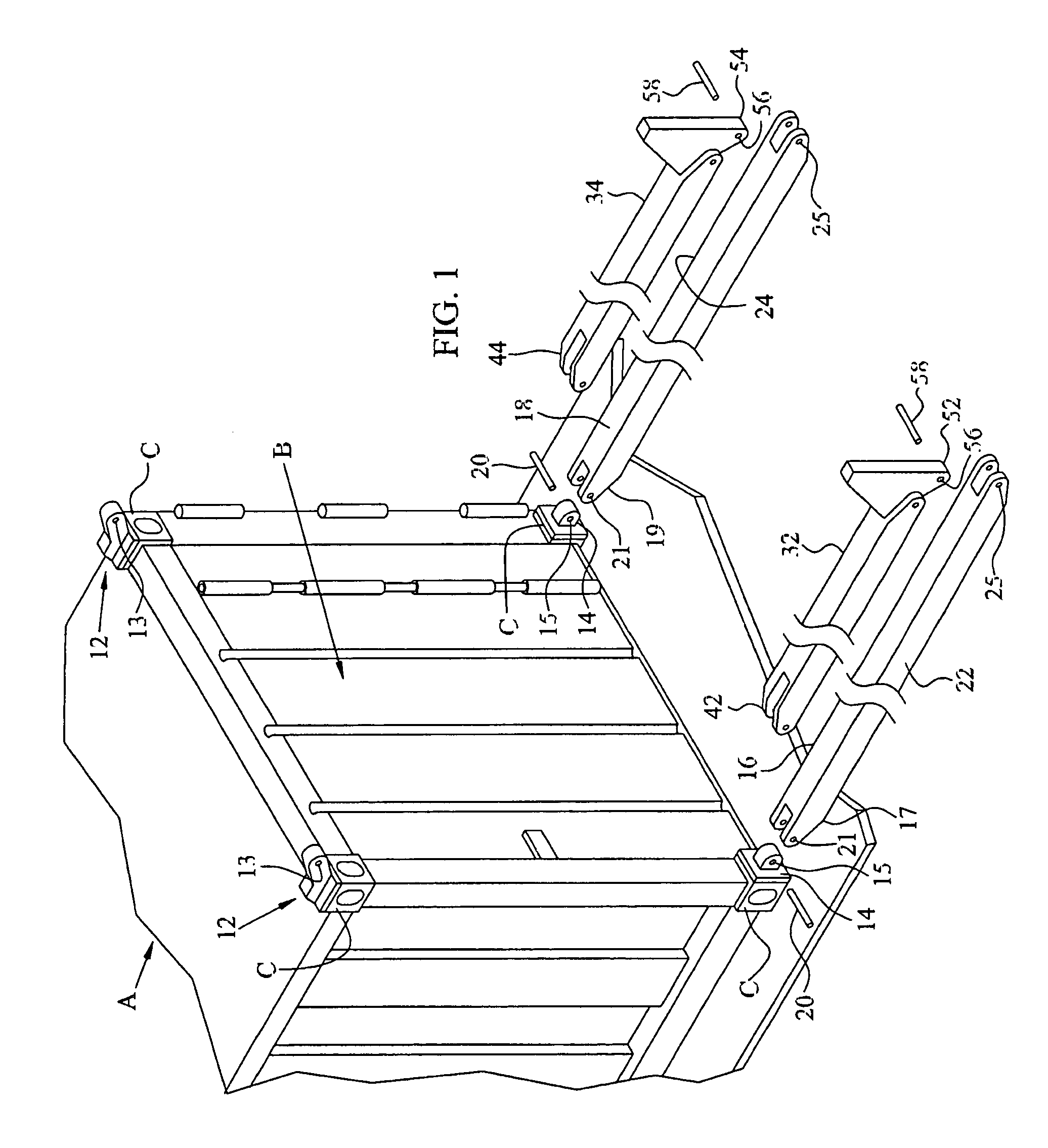
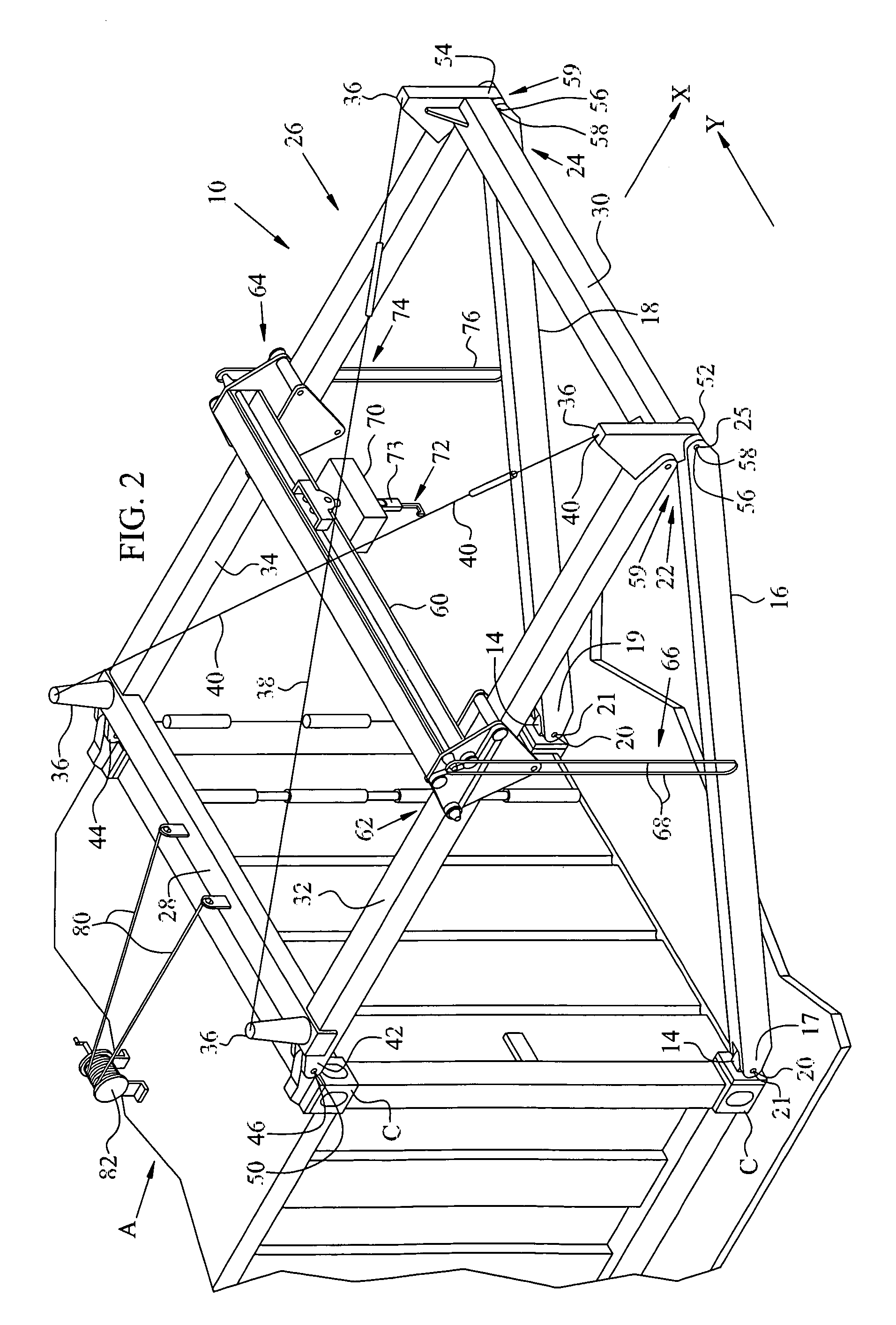
[0022]Referring to FIGS. 1 and 2, X-Y bridge crane 10 of the invention is mounted at one end of a commercial shipping and stowage container A such as an ISO 1161 shipping and stowage container, for example. Bridge crane 10 can be quickly assembled and securely attached to the end of container A by relatively unskilled workmen to provide a means to lift and move goods through doorways or openings at either end of the container. Bridge crane 10 can also be used to support goods and / or other work-pieces at the right height and lateral / longitudinal position adjacent the container's end. Only one closed door B is shown in FIG. 1, and it can be swung open and rotated 270° to an open position behind the container prior to the erection and attachment of bridge crane 10 to allow free, unimpeded transfer of goods. It is within the scope of this invention to allow appropriate modification of structural members to be described to allow opening / closing of door B while bridge crane 10 is in place...


PUM


Abstract

An X-Y bridge crane can be assembled and erected by workmen to lift and move loads at the end of a shipping and stowage container having block-shaped corner fittings at top corners and bottom corners. Rotatable top securing brackets engage the top block-shaped corner fittings and rotatable bottom securing brackets engage the bottom block-shaped corner fittings. Inner end portions of brace members are rotatably connected to the rotatable bottom securing brackets. A framework having inner extensions, outer projecting parts and a laterally extending hoist-traveling beam has inner extensions connected to the top securing brackets and outer projecting parts connected to the outer end portions of the brace members. A hoist is mounted on the hoist-traveling beam to lift and move loads on the framework, and first and second chainfalls connected to the hoist linearly displace the hoist in orthogonal directions.

Description

STATEMENT OF GOVERNMENT INTEREST[0001]The invention described herein may be manufactured and used by or for the Government of the United States of America without the payment of any royalties thereon or therefor.BACKGROUND OF THE INVENTION[0002]This invention relates to a crane mounted on a shipping and stowage container. More particularly, this invention is for a self-erecting crane secured to the end of a shipping and stowage container using powered hoists for lifting / lowering loads and manual force for extending / retracting the lifted loads in the X-direction and transversally moving the loads in the Y-direction.[0003]Containers are widely used in air, sea and land transport of goods since they keep many items together as a lot and protect them from damage during the haul. Large transport vehicles can carry rows and columns of the containers that can rest singly or in stacks on decks and / or pallets.[0004]The great majority of shipping and stowage containers in commercial air and m...

Claims


Application Information

Patent Timeline
Patent Type & Authority Patents(United States)
IPC IPC(8): B66C23/18
CPCB66C23/206B66C23/18
Inventor UPDEGROVE, DARRYLLEAVITT, GARRETT W.SOVEL, JAMES ELLINGTON
Owner USA AS REPRESENTED BY THE SEC OF THE NAVY THE
Why Eureka
Try Eureka