Weight optimized pressurizable aircraft fuselage structures having near elliptical cross sections

a technology of aircraft fuselage and cross section, which is applied in the direction of fuselage, sustainable transportation, transportation and packaging, etc., can solve the problems of substantial engineering design challeng

Inactive Publication Date: 2009-11-24
THE BOEING CO
View PDF7 Cites 15 Cited by
  • Summary
  • Abstract
  • Description
  • Claims
  • Application Information

AI Technical Summary

Benefits of technology

[0005]In accordance with the various exemplary embodiments thereof described herein, the present invention provides an internally pressurizable fuselage structure for an aircraft having a near-elliptical shape and a weight that is minimized by “tailoring,” i.e., optimizing, the structural attributes of substantially every element of the fuselage, expressed as a function of the angular coordinate φ of a cylindrical coordinate system of the fuselage, to react, i.e., to sustain without failure, all design loads incident thereon.
[0010]The exemplary shell has at least one structural attribute associated with every cross-sectional element thereof that has been tailored as a function of the elevation angle φ such that the weight of the shell required to react the design loads incident on that element is less than that required to react the same design load, but wherein the at least one structural attribute has not been so tailored. In a preferred embodiment, the function of φ consists of either R(φ) or Curv(φ). Thus, an exemplary embodiment of a method for weight-optimizing, i.e., minimizing the weight of, the fuselage comprises defining at least one structural attribute of every circumferential element of the shell as a function of either R(φ) or Curv(φ), i.e., as a “functional,” and then tailoring the at least one structural attribute of the element such that the weight of the shell required to react all design loads incident on each circumferential element thereof is less than that required to react the same design loads acting thereon, but wherein the at least one structural attribute has not been so tailored.

Problems solved by technology

However, achieving an optimized, lightweight structure for such near-elliptical cross-section fuselages presents a substantial engineering design challenge because of the structural and weight penalties involved in moving from a fuselage design having a conventional circular cross-section to a fuselage design having a non-circular cross-section, especially those penalties that are associated with pressurization effects inherent in the design of high-altitude jet airliners.

Method used


Image

  • Weight optimized pressurizable aircraft fuselage structures having near elliptical cross sections
  • Weight optimized pressurizable aircraft fuselage structures having near elliptical cross sections
  • Weight optimized pressurizable aircraft fuselage structures having near elliptical cross sections

Examples


Embodiment Construction

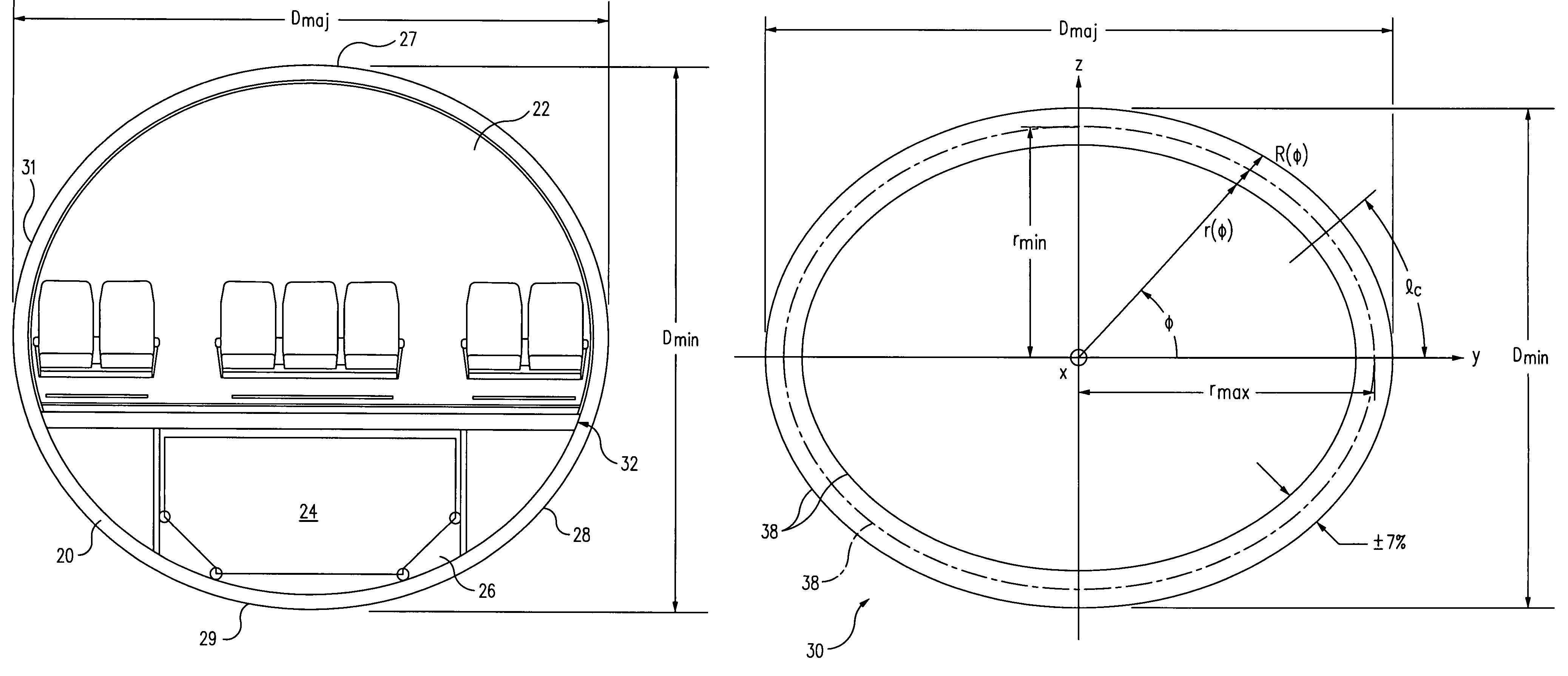
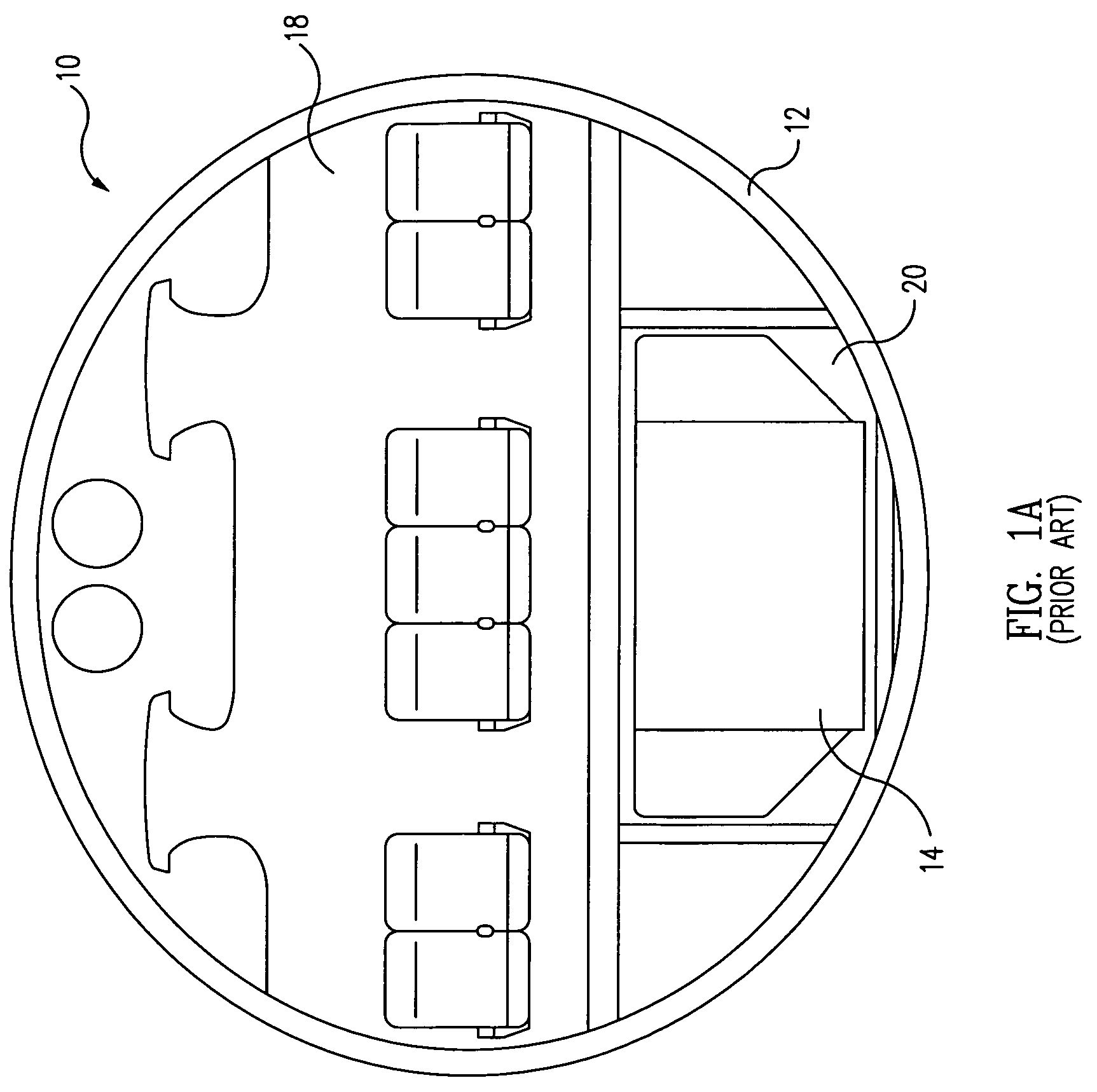
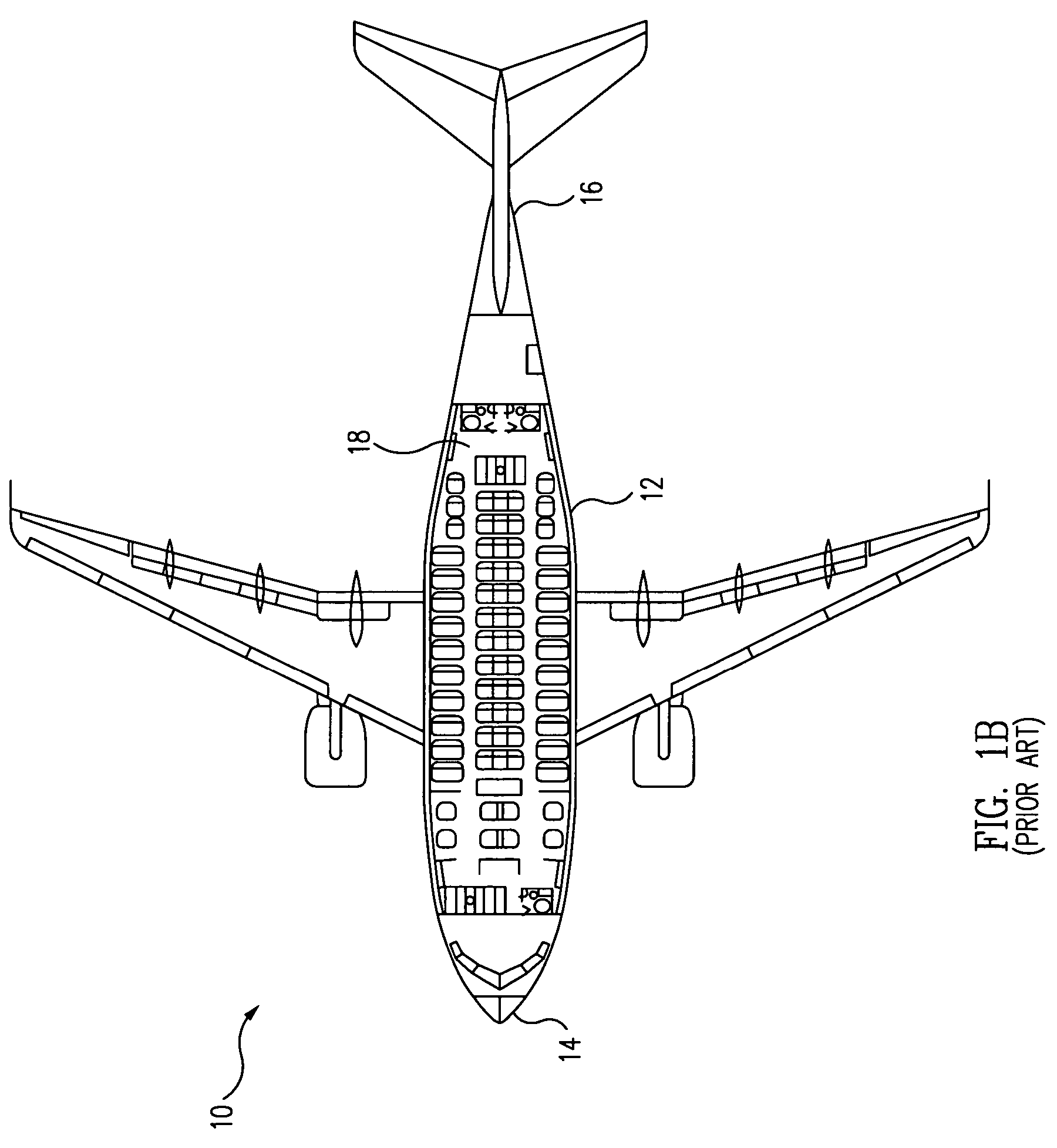
[0024]FIGS. 1A and 1B respectively illustrate cross-sectional front end and plan views of a prior art pressurizable aircraft fuselage 10 having a passenger cabin 18 and a cargo compartment 20. This invention provides a lightweight fuselage shell structure for such an aircraft in which the shell has a near-elliptical cross-section by applying “tailoring,” i.e., optimally selected adjustments, of the structure to more closely match critical design loads as a function of the roll elevation angle φ measured around the centerline axis of the cross-section. An exemplary embodiment of a fuselage shell 20 having a near-elliptical cross-section in accordance with the present invention is illustrated in the front-end cross-sectional view of FIG. 2A. In FIG. 2A, the periphery or outer periphery of the shell is designated 28, and a window belt 31 is disposed adjacent to a passenger cabin 22 having a main cabin floor 32. A cargo compartment 26 is shown with a Unit Load Device or cargo container ...


PUM


Abstract

An aircraft fuselage includes a tubular shell having a centerline axis, opposite ends, and a cross-section having a radius R(φ), where φ is the angular coordinate of a cylindrical coordinate system, a curvature Curv(φ), where Curv(φ) is the inverse of a local radius of curvature of a surface of the shell, and a circumferential shape that varies radially by no more than ±7% from that of an elliptical cross-section at substantially every station along the centerline axis between the nose and tail ends thereof. The weight of the shell is minimized by “tailoring,” i.e., optimizing, at least one structural attribute, expressed as a function of φ, associated with every element of the shell, such that the weight of the shell required to react a design load incident thereon is less than that required to react the same design load, but wherein the same structural attribute has not been so tailored.

Description

TECHNICAL FIELD[0001]This invention relates to aircraft design in general, and in particular, to the design of a lightweight structure for a pressurizable aircraft fuselage having an elliptical or near-elliptical cross-section.BACKGROUND[0002]Certain classes of internally pressurizable aircraft fuselages, such as passenger planes, can beneficially employ near-elliptical cross-sections. For example, U.S. Pat. No. 6,834,833 to M. K. V. Sankrithi discloses the use of an aircraft having a fuselage 10 with a quasi-elliptical, or near-elliptical cross-section that is wider than it is tall. Representative front-end and a top plan cross-sectional views of this class of fuselage shape are illustrated in FIGS. 1A and 1B, respectively, wherein the fuselage comprises a rigid, light weight shell 12 having respective opposite, closed nose and tail ends 14 and 16. This cross-section efficiently encloses a main deck cabin 18, typically provisioned as a spacious and comfortable twin-aisle, seven-abr...

Claims


Application Information

Patent Timeline
Patent Type & Authority Patents(United States)
IPC IPC(8): B64C1/06
CPCB64C1/061B64C1/08B64C2001/0045Y02T50/433B64C2001/0081Y02T50/12B64C2001/0072Y02T50/10Y02T50/40
Inventor SANKRITHI, MITHRA M. K. V.RETZ, KEVIN
Owner THE BOEING CO
Why Eureka
Try Eureka