Driveshaft comprising a counter track joint featuring a delimited axial displacement path

a technology of axial displacement path and drive shaft, which is applied in the direction of couplings for rigid shafts, rotary machine parts, yielding couplings, etc., can solve the problems of axial vibrations being transmitted again, and achieve the effect of avoiding axial vibrations, avoiding axial vibrations, and effectively using vibrations

Inactive Publication Date: 2009-11-24
GKN DRIVELINE INT GMBH
View PDF11 Cites 9 Cited by
  • Summary
  • Abstract
  • Description
  • Claims
  • Application Information

AI Technical Summary

Benefits of technology

[0006]More particularly, it is proposed that the ratio between the total axial displacement S and the pitch circle radius PCR of the balls—when the joint is in the aligned condition—ranges between 0.01 and 0.09 (0.01<SIPCR<0.09). If this axial displacement path referring to the joint size is observed, the axial forces resulting in the operating range of the joint are prevented from becoming to high.
[0008]More particularly, it is proposed that at the first universal joint, the inner face of the outer joint part, the outer face of the inner joint part as well as the outer face and the inner face of the ball cage are each faces of spherical portions, wherein the radial clearance COR between the outer joint part and the ball cage, and the radial clearance CIR between the ball cage and the inner joint part each, ranges between 0.015 and 0.20 mm. This measure allows the production of the first universal joint of this type to be advantageously simplified because those surfaces which, in a joint of this type, do not have a guiding function, but only serve as axial stops, can be produced simply by a forming operation or by a simple turning operation. More particularly, it is proposed that, at the outer joint part, after the forming operation providing the necessary excess dimension needed for machining purposes, the inner spherical guiding face for the ball cage is only soft-tuned and subsequently hardened, whereas the ball tracks are only hardened and ground after the forming operation. The guiding face and the ball tracks can be hardened by induction hardening in one single operation.

Problems solved by technology

However, if an axial displacement takes place under torque load, there are built up axial forces, so that axial vibrations may again be transmitted.

Method used


Image

  • Driveshaft comprising a counter track joint featuring a delimited axial displacement path
  • Driveshaft comprising a counter track joint featuring a delimited axial displacement path
  • Driveshaft comprising a counter track joint featuring a delimited axial displacement path

Examples


Embodiment Construction

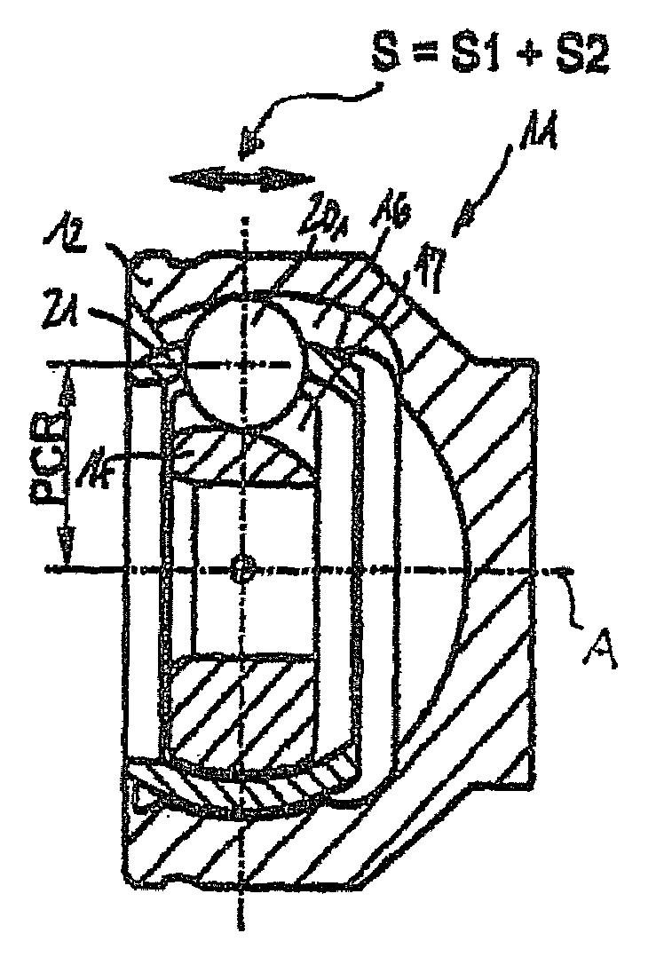
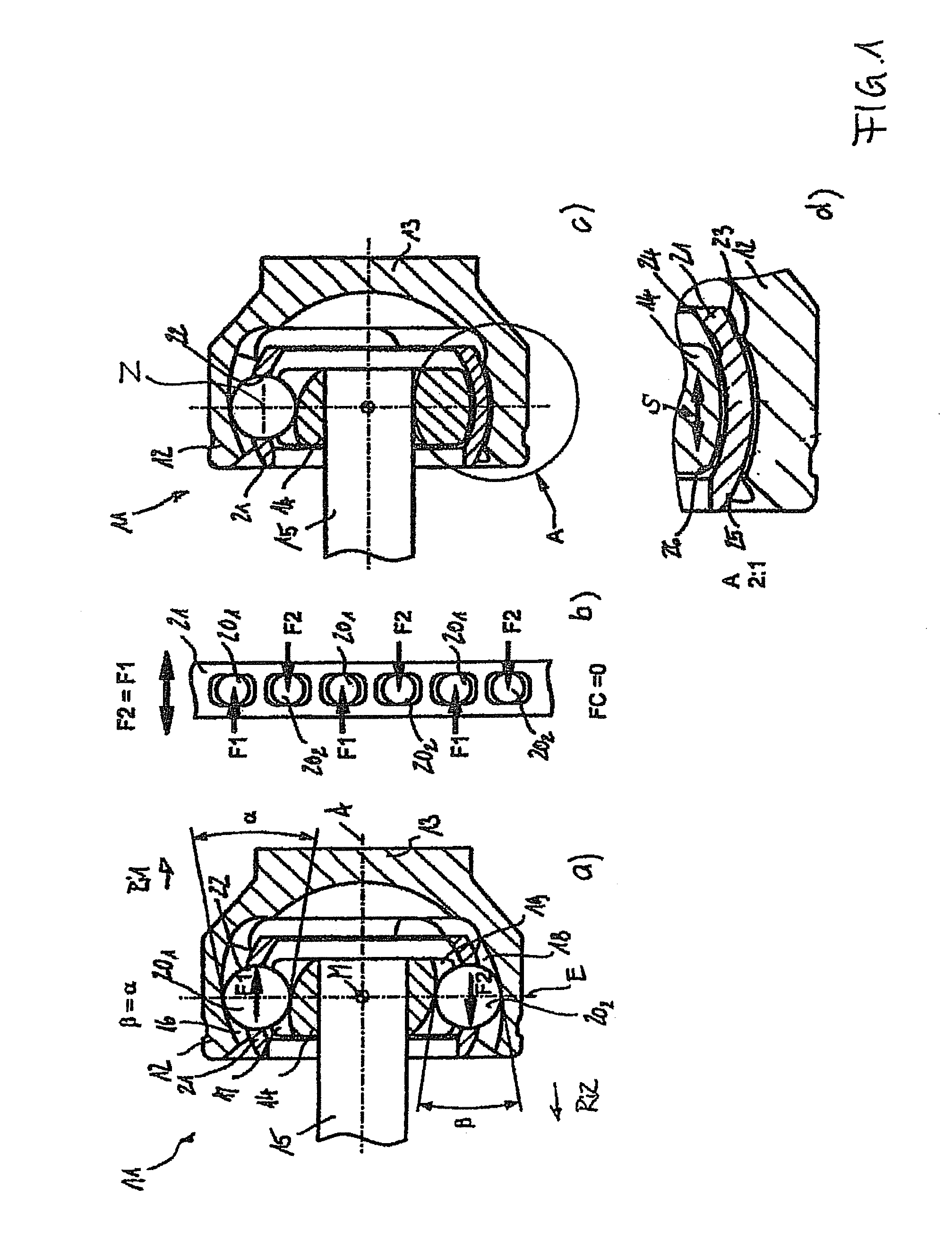
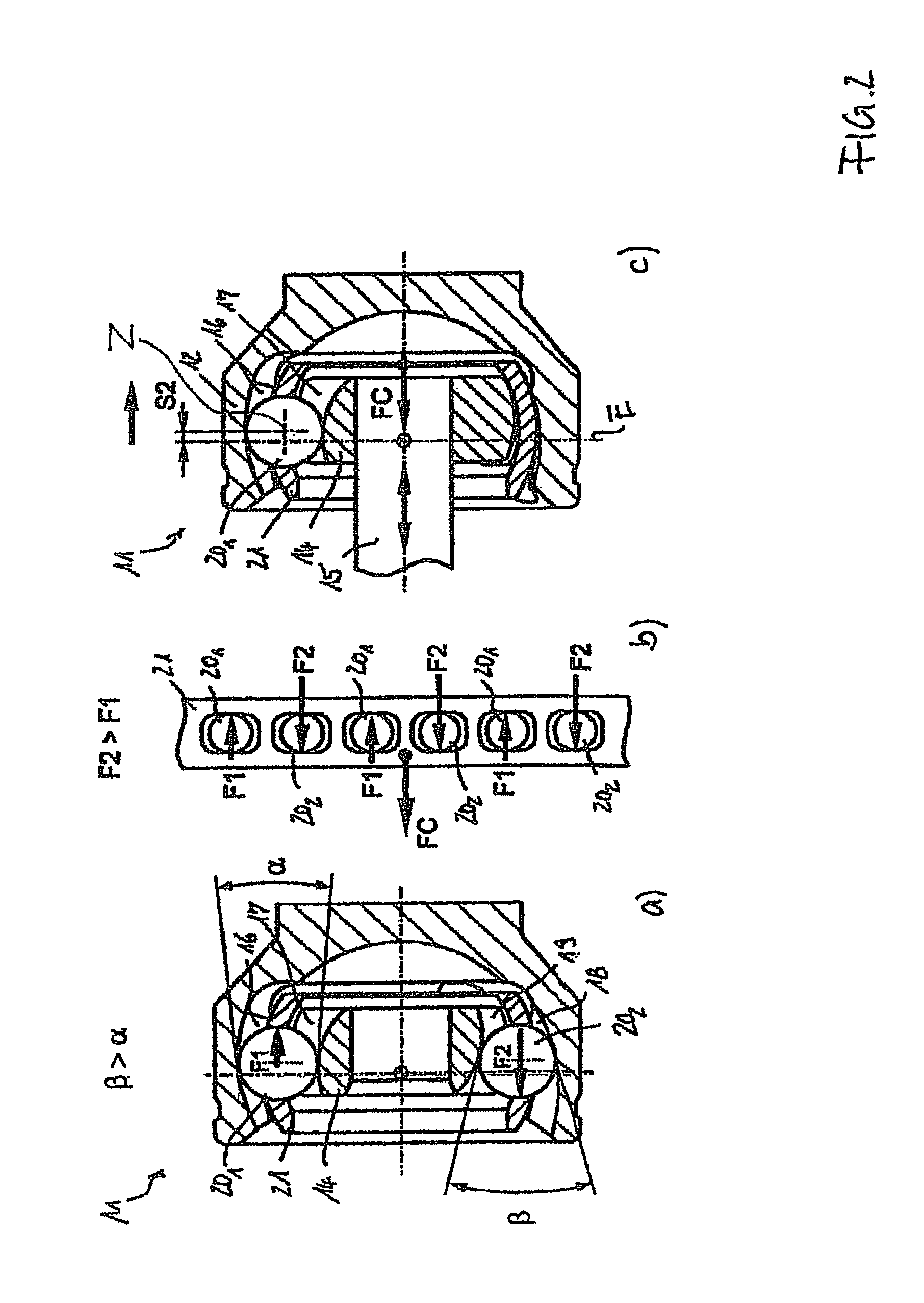
[0057]The illustrations of FIG. 1 will be described jointly below. An inventive counter track joint 11 comprises an outer joint part 12 with a formed-on base 13, an inner joint part 14 with an inserted shaft 15, pairs of tracks consisting of first outer ball tracks 16 and first inner ball tracks 17 which open in a central joint plane E in a first direction Ri1 towards the base 13, as well as second pairs of tracks consisting of second outer ball tracks 18 and second inner ball tracks 19 which open in a central joint plane E in a second axial direction Ri2 towards the shaft 15. A plurality of first and second pairs of tracks 16, 17 is distributed around the joint circumference. The opening angle of the first pairs of tracks 16, 17 in the central plane E has been given the symbol α; the opening angle of the second pairs of tracks 18, 19 in the central plane E has been given the symbol β. In the pairs of tracks there are accommodated first balls 201 and second balls 202 whose ball cent...


PUM


Abstract

A constant velocity universal ball joint 11 having first and second outer ball tracks 16, 18, and first and second inner ball tracks 17, 19, forming first pairs of tracks 16, 17 which widen in a first axial direction Ri1 (α), and forming second pairs of tracks 18, 19 which widen in a second axial direction Ri2 (β). Balls 20 are guided in the pairs of tracks and have centers Z positioned on a pitch circle radius PCR around a joint centre M. A ball cage 21 holds the balls 20 in a common central plane E on to the angle-bisecting plane when the joint is articulated. There is provided an axial clearance permitting a relative axial displacement S wherein, when in the aligned condition, the ratio between the axial clearance S and the pitch circle radius PCR ranges between 0.01 and 0.09 (0.01<S / PCR<0.09).

Description

RELATED APPLICATIONS[0001]This application is a continuation of and claims the benefit of PCT Application No. PCT / EP2006 / 005990 filed on Jun. 22, 2006 (claiming priority from currently pending German Application No. 10 2005 042 909.2 filed Sep. 8, 2005), entitled “Driveshaft Comprising A Counter Track Joint Featuring A Delimited Axial Displacement Path”and PCT Application No. PCT / EP2006 / 005991 filed on Jun. 22, 2006 (claiming priority from currently pending German Application No. 10 2005 042 910.6 filed Sep. 8, 2005) entitled “Counter Track Joint With Limited Axial Displacement.”TECHNICAL FIELD[0002]The invention relates to a driveshaft comprising a first universal joint, an intermediate shaft and a second universal joint, wherein the first universal joint is a constant velocity universal ball joint in the form of a counter track joint.BACKGROUND OF THE INVENTION[0003]Counter track joints of the type used as a first universal joint are described in DE 100 60 120 A1, and it is assume...

Claims


Application Information

Patent Timeline
Patent Type & Authority Patents(United States)
IPC IPC(8): F16D3/224
CPCF16D1/101F16D3/06F16D3/202F16D3/2233F16D3/38F16D3/2245F16D2003/22323F16D2001/103F16D2003/22303F16D2003/22306F16D3/2055Y10S464/906
Inventor WECKERLING, THOMASERYILMAZ, ORKAN
Owner GKN DRIVELINE INT GMBH
Why Eureka
Try Eureka