Measurements of yield stress and plastic viscosity of cement-based materials via concrete rheometer

a technology of concrete rheometer and yield stress, which is applied in the direction of clay preparation apparatus, instruments, mixing, etc., can solve the problems of aggregates stuck between the inner wall of the cylindrical vessel and the vane, and achieve the effect of reducing the disturbance of concr

Inactive Publication Date: 2009-12-01
JAU WEN CHEN
View PDF5 Cites 17 Cited by
  • Summary
  • Abstract
  • Description
  • Claims
  • Application Information

AI Technical Summary

Benefits of technology

[0006]Another purpose of the present invention is to provide a rheometer (concrete rheometer). It is feasible to measure the plastic viscosity and yield stress of cement-based materials by the concrete rheometer, and compare with slump flow test, V-funnel times, J-Ring test and U-box test. The main source of error for two point test apparatus as mentioned by previous researches comes from segregation caused by disturbance and the gap width. A gap width smaller than the maximum aggregate size may cause the aggregates stuck between vane and the inner wall of the cylindrical vessel. Therefore, the invention uses larger diameter and a high-capacity cylindrical vessel to avoid the disturbance and the small gap problem such that the ratio of r1 / r0 is between 0.1˜0.6. The gap width (r0−r1) is at least 2.5 times of maximum aggregate size which prevents the aggregates from being stuck and to avoid the friction from wall of cylinder which may cause an error to the measured torque. The rotational speed of rotation shaft is preferably set over 0.001 rad / s. In such case, it is more feasible to measure the torque, and reduce greatly the disturbance of concrete, thus making rheometer become an accurate rheology testing instrument.

Problems solved by technology

The main source of error for two point test apparatus as mentioned by previous researches comes from segregation caused by disturbance and the gap width.
A gap width smaller than the maximum aggregate size may cause the aggregates stuck between vane and the inner wall of the cylindrical vessel.

Method used


Image

  • Measurements of yield stress and plastic viscosity of cement-based materials via concrete rheometer
  • Measurements of yield stress and plastic viscosity of cement-based materials via concrete rheometer
  • Measurements of yield stress and plastic viscosity of cement-based materials via concrete rheometer

Examples


embodiment 1

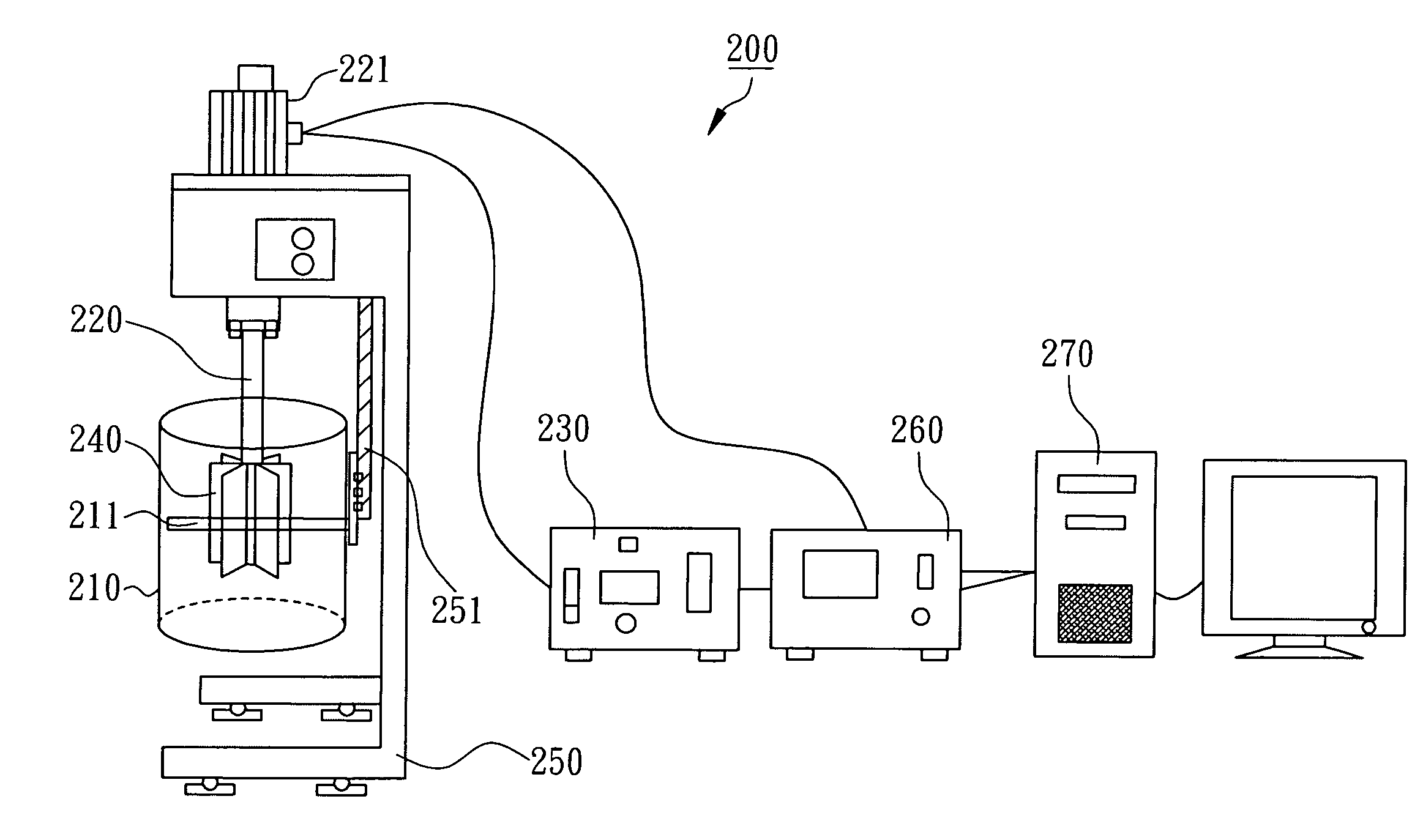
[0051]Referring to FIGS. 3 and 6, a rheometer 200 of the preferred embodiment of the present invention could determine yield stress and viscosity of cement-based materials. The rheometer 200 includes a drum 210, a rotation shaft 220, a rotational speed controller 230, and an vane-A 240. The drum 210 is used to accommodate cement-based materials, e.g. concrete, mortar or cement paste. One end of the rotation shaft 220 is screwed into foundation 250, and powered by a drive motor 221. The other end of rotation shaft 220 is pushed into the drum 210. The rotational speed controller 230 is used to adjust the rotational speed of rotation shaft 220, such that the rotation shaft 220 could rotate slowly at given speed. In addition, the rheometer 200 further includes a torque display 260 and a data collector 270. The drum 210 is connected to a drum supporting bar 211, and the foundation 250 is fitted with a drum elevating bar 251, which is linked to the drum supporting bar 211 to ensure elevat...

embodiment 2

[0052]Referring to FIG. 7, a rheometer 300, of which the metal shaft 320 is not connected to the motor. Instead, the drive motor 330 is connected to a metal tenon 361 of the drum 310 by a metal disk 360, thus, during testing, the motor 330 drives the drum 310, in turn, driving the concrete and vane-A 240, enabling the measurement of torque of the metal shaft 320.

[0053]The rheometer 300 includes a drum 310, a shaft 320, a rotational speed controller 230, and a vane-A 340. The drum 310 is used to accommodate cement-based materials, e.g. concrete, mortar or cement paste and the surface of the drum 310 has serrated surfaces that no slippage occurred. One end of the metallic shaft 320 is screwed into foundation 350, the other end of metallic shaft 320 is pushed into the drum 310, and powered by a drive motor 330. The rotational speed controller 230 is used to adjust the rotational speed of rotation drum 310, such that the rotation drum 310 could rotate slowly at given speed. In addition,...

embodiment 3

[0056]Referring to FIG. 9, a preferred embodiment of the present invention, of which a rheometer 500 to measure the rheology of cement-based materials, includes a rotation drum 510, bearings 520, 530, a rotational speed controller 230; the rotation drum 510 can store cement-based materials, such as concrete, mortar, or cement paste, and the inside of the rotation drum 510 has blades to mix the concrete; the rotation drum 510 has a set of gearwheel 515, which is driven by a transmission motor 521; the rotational speed controller 230 can adjust the rotational speed slowly at given speed for the rotation drum 510; the bearing 520 goes through a foundation 540, and the bearing 530 is hollow and goes through a foundation 540, and are connected to inlet 550 and outlet 560; the rheometer 500 can also comprise a torque display 260 and a data collector 270.


PUM

PropertyMeasurementUnit
volumeaaaaaaaaaa
heightaaaaaaaaaa
heightaaaaaaaaaa

Abstract

A rheometer can be used to measure yield stress and viscosity of a cement-based material with excellent results. It mainly includes a drum and at least one adaptive vane assembly. The adaptive vane assembly is replaceably connected to a shaft. The shaft rotates relative to the drum. The ratio of radius (r1) of the adaptive vane assembly to radius (r0) of the drum is between 0.1˜0.6. The shaft is rotated with a minimum rotational speed more than 0.001 rad / s, and then can measure its torque at constant speed. Accordingly, the rheometer can greatly reduce the disturbance of vanes of the adaptive vane assembly upon the cement-based materials and reduce the slippage among particles and the vanes. Moreover, the minimum shear stress is defined as a yield stress.

Description

FIELD OF THE INVENTION[0001]The present invention relates generally to a new generation of rheometer, and more particularly to an improved one which is suitable to measure the rheology of cement-based materials (e.g. concrete, mortar, cement paste).BACKGROUND OF THE INVENTION[0002]To measure the rheology of various liquids, rheometers were designed in many different types, of which a typical rheometer can measure both the rheology of cement-based materials (e.g. concrete), and also the viscosity (η) and yield stress (τy), as illustrated in two-point test in FIG. 1. The rheometer 100 includes a drum 110 to accommodate concrete, and a rotation shaft 120 driven by a motor 130 and connected to a plurality of vanes 121. This theory was initiated by G H Tattersall, and the rheology of concrete is simulated as Bingham fluid, for which a shear stress similar to static friction would exist prior to the initiation of shear strain. Only when the shear stress reaches a specific value, the shear...

Claims


Application Information

Patent Timeline
Patent Type & Authority Patents(United States)
IPC IPC(8): G01N11/14
CPCG01N11/14G01N33/383G01N2203/0676
Inventor JAU, WEN-CHEN
Owner JAU WEN CHEN
Why Eureka
Try Eureka