Methods and compositions for thermally treating a conduit used for hydrocarbon production or transmission to help remove paraffin wax buildup

a technology of hydrocarbon production or transmission, which is applied in the direction of insulation, physical/chemical process catalysts, wellbore/well accessories, etc., can solve the problems of lowering oil production, obstructing flow, and interfering with transportation

Active Publication Date: 2009-12-01
HALLIBURTON ENERGY SERVICES INC
View PDF8 Cites 63 Cited by
  • Summary
  • Abstract
  • Description
  • Claims
  • Application Information

AI Technical Summary

Benefits of technology

[0038]According to one aspect of the invention, a method is provided for increasing the temperature of a section of conduit used for the production or transmission of hydrocarbon. The method comprises the step of: forming a treatment fluid comprising: (i) a carrier fluid; and (ii) a first reactant and a second reactant. The first reactant and second reactant are selected for being capable of reacting together in an exothermic chemical reaction; and the first and second reactant are in at least sufficient concentrations in the carrier fluid to generate a theoretical heat of reaction of at least 1,000 kJ / liter of the treatment fluid. At least some of at least one of the first reactant and the second reactant is suspended in the carrier fluid in a solid form that is adapted to help control the release of the reactant into the carrier fluid. The method further comprises the step of: introducing the treatment fluid into a section of conduit used for the production or transmission of hydrocarbon.
[0040]After introducing the treatment fluid into the conduit, the treatment fluid is preferably allowed to heat the conduit to help melt the paraffin wax deposits. The treatment fluid preferably includes a liquid hydrocarbon that is a liquid at standard temperature and pressure, which can help dissolve and remove the paraffin wax. The treatment fluid can then be displaced from the section of conduit and help remove the paraffin wax from the section of conduit.
[0045]The solid form of a reactant or comprising a reactant can be, for example, a pure solid, undissolved form of the reactant, a solid matrix of material with the reactant embedded in the matrix, a solid encapsulation of a liquid or solid material with the reactant therein, or any combination in any proportion of any one or more of the foregoing. The solid form is adapted to help control the initial release of the reagent into solution and / or the rate of release of the reagent into solution. This helps control the initiation and / or the rate of reaction between the reactants, respectively, which helps control when the heat of reaction is released. As described in the detailed description of the invention, several different examples of techniques are provided for having at least one of the reactants in a solid form, which are adapted to control the mixing of the reactants in a carrier fluid and the generation of the heat of reaction.
[0047]It is also possible to use the methods according to the invention to delay the initiation of the exothermic reaction, and thereby delay the initiation of release of heat energy. This can be used, for example, to allow time for the treatment fluid to reach a desired portion of a conduit that may have paraffin deposits.

Problems solved by technology

Paraffin wax deposition obstructs the flow of oil, lowering oil production and interfering with transportation.
But as crude oil flows through the production tubulars from the hydrocarbon-bearing formation through the wellbore toward the surface, the surrounding temperature of the wellbore tends to decline toward the surface, allowing heat to dissipate from the fluid and causing the hydrocarbon fluid to begin to cool.
This can be particularly problematic in subsea pipelines because the surrounding water on the seafloor is very cold, typically about 39° F.
To help prevent paraffin deposits, some cross-country pipelines are heated, which is very costly.
However, this is not feasible for subsea pipelines, which are in direct contact with the surrounding cold seawater.
Unless at least some of the buildup is removed from time to time, eventually the deposits can increase to the point where the conduit becomes choked.
Also, sometimes some of the paraffin deposits will release from the inside wall of a pipeline and cause a blockage.
Such a blockage can occur anywhere in the pipeline.
The mechanical approaches are used specially for production strings and pipeline conduits, as they are generally unsuitable for use in a subterranean formation or at the interface between a formation and a wellbore.
This type of mechanical cleaning device is called a “pig” because the scraping of the inner wall of the pipeline makes a tremendous squealing noise.
But if paraffin buildup on the inner walls of the pipeline is heavy, as the pig moves forward it will collect so much paraffin in front of the moving pip that it blocks any further movement of the pig.
In other words, as more and more paraffin is scraped off the inner walls of the pipeline and accumulates in front of the moving pig, at some point the pumping pressure in the pipeline is not enough to push the pig and all the accumulated paraffin further through the pipeline, at which point the pipeline is plugged.
However, hot water does not dissolve or dilute the paraffin wax, so the water and melted paraffin wax can form an undesirable oil / water emulsion.
Another disadvantage to using hot water, however, is that it can contribute to corrosion problems with the metal conduits.
Nearly 61 meters above the perforations, the reaction rate increases and produces huge amounts of heat, the temperature reaching a thermal maximum, heat being lost to the environment, with consequent reduction in the temperature of the spent solution.

Method used


Image

  • Methods and compositions for thermally treating a conduit used for hydrocarbon production or transmission to help remove paraffin wax buildup
  • Methods and compositions for thermally treating a conduit used for hydrocarbon production or transmission to help remove paraffin wax buildup
  • Methods and compositions for thermally treating a conduit used for hydrocarbon production or transmission to help remove paraffin wax buildup

Examples


Embodiment Construction

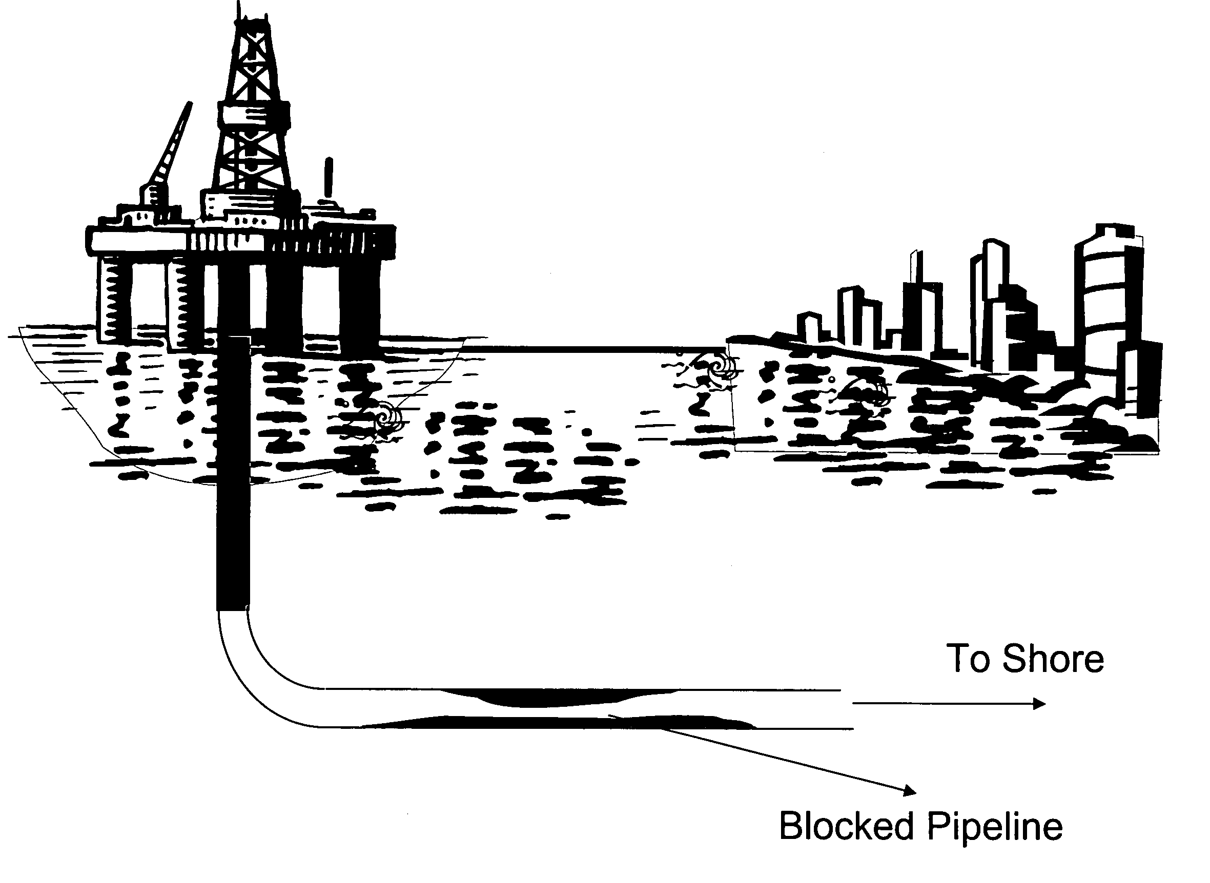
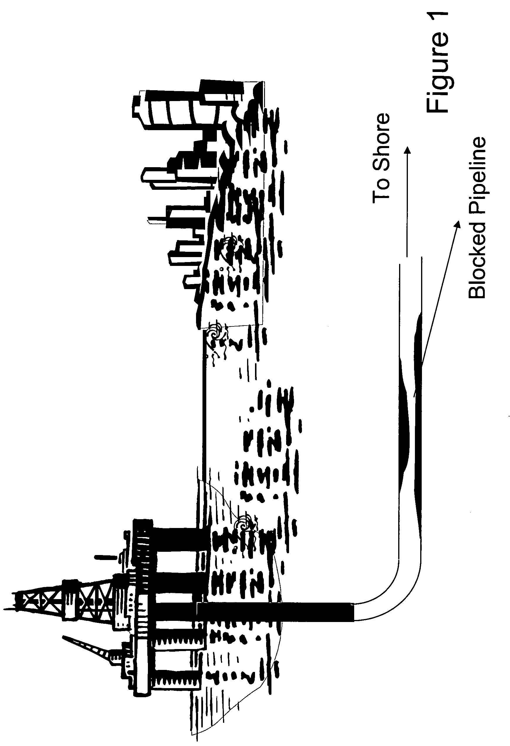
[0058]The invention provides for new methods for controlling an exothermic reaction in a treatment fluid, which can be used to facilitate the dissolution and cleanup of paraffin wax buildup in conduits used for hydrocarbon production or transmission. This paraffin deposition leads to reduced crude oil flow and under extreme conditions leads to complete blockage of the pipelines, as previously discussed and as illustrated in FIG. 1.

[0059]“Wax” is a low-melting organic mixture or compound of relatively high molecular weight, solid at room temperature and generally similar in composition to fats and oils except that it contains no glycerides. Some are hydrocarbons; others are esters of fatty acids and alcohols. They are classed among the lipids. Waxes are thermoplastic, but since they are not high polymers, are not considered in the family of plastics. Common properties are water repellency, smooth texture, low toxicity, freedom from objectionable odor and color. They are combustible a...


PUM

PropertyMeasurementUnit
temperatureaaaaaaaaaa
temperaturesaaaaaaaaaa
formation temperaturesaaaaaaaaaa

Abstract

Methods are provided for increasing the temperature of a section of conduit used for the production or transmission of hydrocarbon. According to one aspect, the method includes the steps of: (a) forming a treatment fluid comprising: (i) a carrier fluid; and (ii) a first reactant and a second reactant; and (b) introducing the treatment fluid into a section of conduit used for the production or transmission of hydrocarbon. The first reactant and second reactant are selected for being capable of reacting together in an exothermic chemical reaction; and the first and second reactant are in at least sufficient concentrations in the carrier fluid to generate a theoretical heat of reaction of at least 1,000 kJ / liter of the treatment fluid. At least some of at least one of the first reactant and the second reactant is suspended in the carrier fluid in a solid form that is adapted to help control the release of the reactant into the carrier fluid.

Description

CROSS-REFERENCE TO RELATED APPLICATIONS[0001]Not Applicable.STATEMENT REGARDING FEDERALLY SPONSORED RESEARCH OR DEVELOPMENT[0002]Not Applicable.REFERENCE TO A MICROFICHE APPENDIX[0003]Not applicable.TECHNICAL FIELD[0004]The invention generally relates to the methods for warming a conduit used for hydrocarbon production or transmission to help remediate paraffin wax buildup. More particularly, the invention relates to forming a treatment fluid with reactants that react exothermically to produce heat in a controlled manner and introducing the treatment fluid into the conduit to warm the pipeline. The heat can be used to help remove paraffin wax deposits.BACKGROUND[0005]Hydrocarbon, such as crude oil, for making various grades of fuels and oils, is produced by drilling wells into the earth, either on land or under sea. Crude oil contains many kinds of hydrocarbons, including paraffin wax.[0006]Paraffin wax deposition is found practically whenever hydrocarbon (e.g., crude oil) is produc...

Claims


Application Information

Patent Timeline
Patent Type & Authority Patents(United States)
IPC IPC(8): B08B9/027B08B7/00F16L53/30
CPCF17D1/18F17D1/17C09K8/524E21B36/008E21B37/06F17D3/16B08B9/027C09K8/536B01J31/04B01J31/06E21B43/01F16L53/30
Inventor SARKAR, DIPTABHASARRINGTON, STEPHEN T.POWELL, RONALD J.ROBB, IAN D.TODD, BRADLEY L.
Owner HALLIBURTON ENERGY SERVICES INC
Why Eureka
Try Eureka