Controllably feeding powdered or granular material

a technology of granular material and powder, which is applied in the direction of vacuum evaporation coating, chemical vapor deposition coating, coating, etc., can solve the problems of significant degradation, changes in the structure of the molecules and associated changes in the material properties, and the use of organic materials in the manufacture of oled devices are often subject to degradation, so as to facilitate the flow of powdered, reduce power consumption, and improve the effect of feed uniformity

Active Publication Date: 2009-12-01
GLOBAL OLED TECH
View PDF14 Cites 12 Cited by
  • Summary
  • Abstract
  • Description
  • Claims
  • Application Information

AI Technical Summary

Benefits of technology

[0010]It is therefore an object of the present invention to provide an effective way to vaporize powders.
[0014](c) agitating or fluidizing the powdered or granular material in proximity to the feeding location in cooperation with the rotatable auger so as to facilitate the flow of powdered or granular material through the opening(s) to the heated surface where the powdered or granular material is vaporized.
[0015]An advantage of this invention is that it provides controlled delivery of powdered or granular material with reduced expenditures of power. Feed uniformity is substantially improved.

Problems solved by technology

The organic materials used in the manufacture of OLED devices are often subject to degradation when maintained at or near the desired rate dependant vaporization temperature for extended periods of time.
Exposure of sensitive organic materials to higher temperatures can cause changes in the structure of the molecules and associated changes in material properties.
In this manner, the material is consumed before it has reached the temperature exposure threshold to cause significant degradation.
The limitations with this practice are that the available vaporization rate is very low due to the limitation on heater temperature, and the operation time of the source is very short due to the small quantity of material present in the source.
The low deposition rate and the frequent and time consuming process associated with recharging a source has placed substantial limitations on the throughput of OLED manufacturing facilities.
A secondary consequence of heating the entire organic material charge to roughly the same temperature is that it is impractical to mix additional organic materials, such as dopants, with a host material unless the vaporization behavior and vapor pressure of the dopant is very close to that of the host material.
This is generally not the case and as a result, prior art devices frequently require the use of separate sources to co-deposit host and dopant materials.
This restriction has imposed a substantial limitation on the architecture of OLED devices, increases the necessary size and cost of the vacuum deposition chamber and decreases the reliability of the system.
This gradient co-deposition is unavoidable in prior art sources where a single material is vaporized from each of multiple sources.
A further limitation of prior art sources is that the geometry of the interior of the vapor manifold changes as the organic material charge is consumed.

Method used


Image

  • Controllably feeding powdered or granular material
  • Controllably feeding powdered or granular material
  • Controllably feeding powdered or granular material

Examples


Embodiment Construction

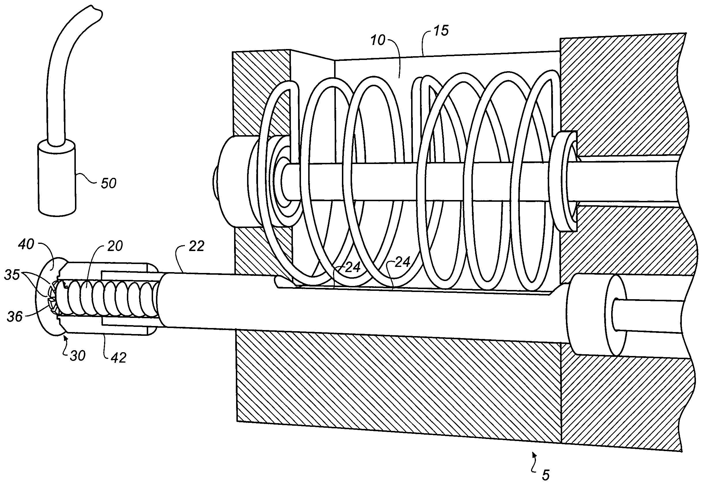
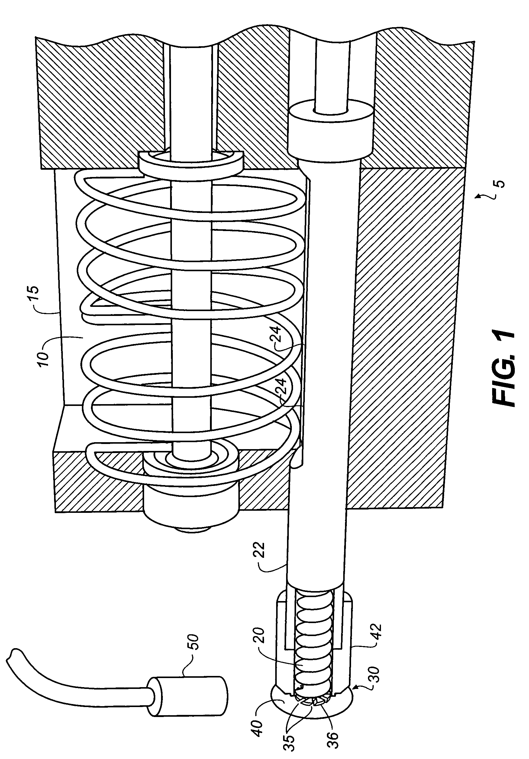
[0021]Turning now to FIG. 1, an apparatus 5 for metering powdered or granular material 10 such as organic material into a heated surface 40 is shown. The apparatus 5 is includes a container 15 which holds material 10. Material 10 can have one or more components and can be powdered or granular. A rotatable auger 20 is disposed in an auger enclosure 22 which in turn is disposed in a material receiving relationship with the container 15. The auger enclosure 22 has openings 24 for receiving material 10 from the container 5. The rotatable auger 20 moves material 10 along a feed path 25 to a feeding location 30. Rotation of the rotatable auger 20 causes the material 10 to be subject to pressure at the feeding location 30. This pressure forces the material 10 through one or more openings 35 formed in a member 36. Member, 36 can be attached to the rotatable auger 20 so that the member 36 rotates with the rotatable auger 20, and carries material 10 into contact with a heated surface 40 where...


PUM

PropertyMeasurementUnit
particle sizeaaaaaaaaaa
thermally conductiveaaaaaaaaaa
pressureaaaaaaaaaa

Abstract

A method for metering powdered or granular material onto a heated surface to vaporize such material. The method comprises providing a rotatable auger d for receiving powdered or granular material and as the rotatable auger rotates, such rotatable auger translates such powdered or granular material along a feed path to a feeding location. The method also providing at least one opening at the feeding location such that the pressure produced by the rotating rotatable auger at the feeding location causes the powdered or granular material to be forced through the opening onto the heated surface in a controllable manner. The material is agitated or fluidized proximate to the feeding location.

Description

CROSS-REFERENCE TO RELATED APPLICATIONS[0001]Reference is made to commonly assigned U.S. Pat. No. 7,232,588 issued Jun. 19, 2007, by Michael Long et al, entitled “Device and Method for Vaporizing Temperature Sensitive Materials”, U.S. Pat. No. 7,288,285 issued Oct. 30, 2007, by Michael Long et al, entitled “Delivering Organic Powder to a Vaporization Zone”, U.S. Pat. No. 7,288,286 issued Oct. 30, 2007, by Michael Long et al, entitled “Delivering Organic Power to a Vaporization Zone”, U.S. Patent Publication No. 2006 / 0177576 published Aug. 10, 2006, by Michael Long et al, entitled “Controllably Feeding Organic Material in Making OLEDS”, and U.S. Pat. No. 7,213,347 issued May 8, 2007, by Michael Long et al, entitled Metering Material To Promote Rapid Vaporization” the disclosures of which are incorporated herein by reference.FIELD OF THE INVENTION[0002]The present invention relates to making devices by vaporizing material and more particularly to controllably feeding material to a hea...

Claims


Application Information

Patent Timeline
Patent Type & Authority Patents(United States)
IPC IPC(8): C23C16/00
CPCC23C16/448C23C14/246
Inventor LONG, MICHAELREDDEN, NEIL P.KOPPE, BRUCE E.PALONE, THOMAS W.
Owner GLOBAL OLED TECH
Why Eureka
Try Eureka