

Electric rotating machine having permanent magnets and method of manufacturing teeth portions of the stator iron core
a technology of permanent magnets and rotating machines, which is applied in the direction of dynamo-electric machines, wind energy generation, magnetic circuit shapes/forms/construction, etc., can solve the problems of difficult design of rotating machines using magnets with high energy products, difficult mechanical working of stators, and difficult design to obtain the maximum efficiency of rotating machines, etc., to achieve the effect of reducing torque loss and torque vibration
- Summary
- Abstract
- Description
- Claims
- Application Information
AI Technical Summary
Benefits of technology
Problems solved by technology
Method used
Image

Examples
Embodiment Construction
[0002]1. Field of the Invention
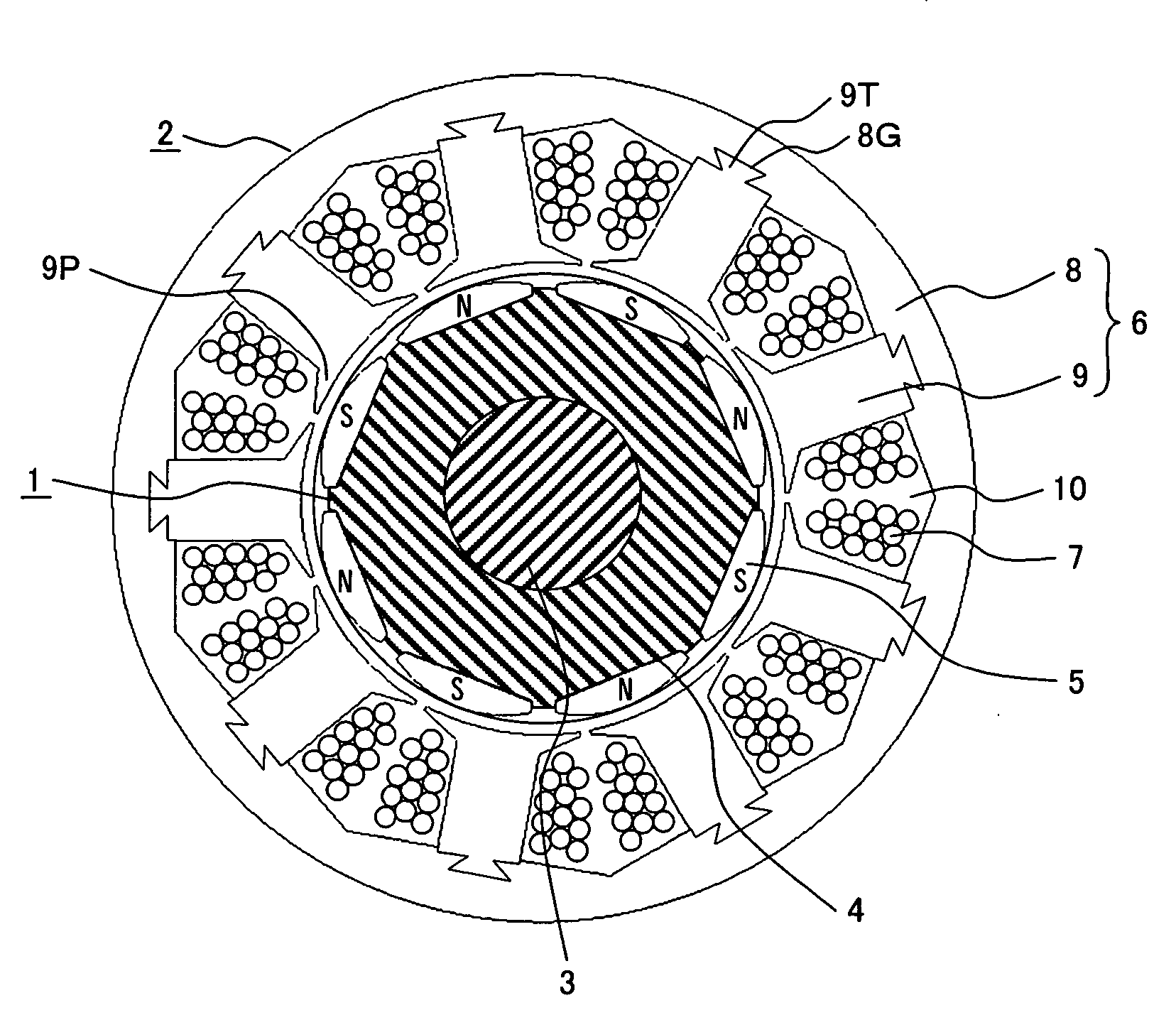
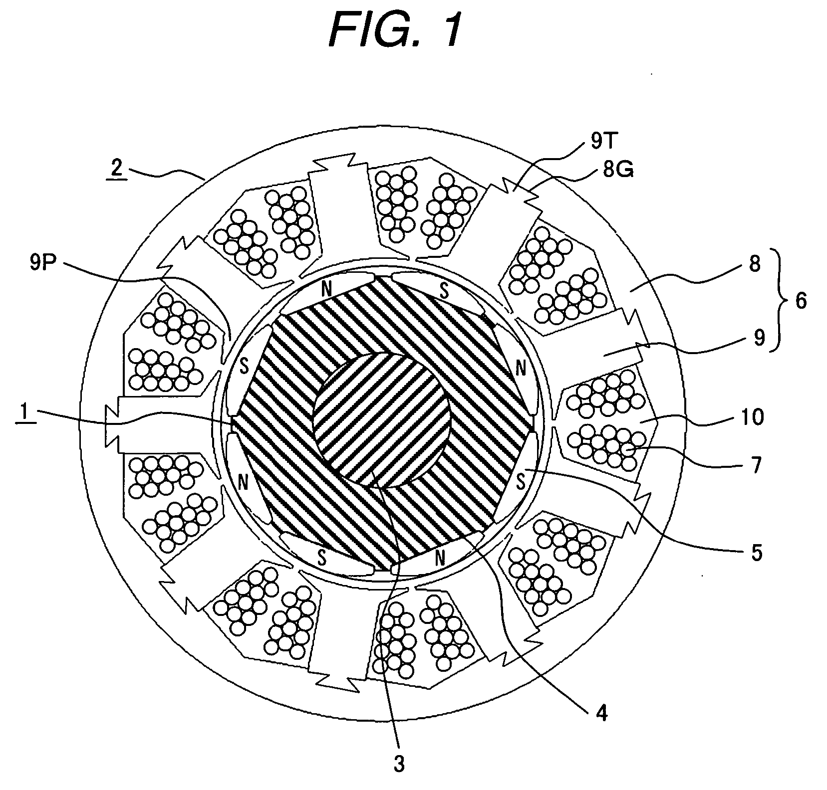
[0003]The present invention relates to an electric rotating machine such as motors, generators, etc and a method of manufacturing teeth portions of a stator iron core of the rotating machine, more particularly to an electric rotating machine having permanent magnets in the rotor and a method of manufacturing the teeth portions of the stator iron core.
[0004]2. Related Art
[0005]Generally, a motor converts electric energy into mechanical energy and a generator converts mechanical energy into electrical energy. Both of them require high conversion efficiency; they are designed to have a highest conversion efficiency at the rated output. The efficiency of the rotating machines is represented by a value of dividing an output by an input, and the difference between the output and the input is a loss such as copper loss or iron loss.
[0006]In order to increase efficiency of the electric rotating machine and to downsize the electric rotating machine, magnets con...
PUM
 Abstract
Description
Claims
Application Information