
Method of detecting the relative positioning of two signals and corresponding device

a technology of relative positioning and detection method, which is applied in the direction of transmission, transmission system, pulse automatic control, etc., can solve the problems of instability and the approach of the prior art that greatly complicate the management of the clock domain, and achieve the effect of limiting the risk of data loss and more tim

Active Publication Date: 2009-12-01
STMICROELECTRONICS SRL
View PDF28 Cites 2 Cited by
  • Summary
  • Abstract
  • Description
  • Claims
  • Application Information

AI Technical Summary

Benefits of technology

[0005]For example, if one wishes to transmit information of the domain regulated by the clock having the higher frequency to the domain regulated by the clock having the lower frequency, it is preferable to perform the transmission on the first edge of the signal of the clock at high frequency corresponding to an edge of the signal of the clock at low frequency. One thus benefits from more time for performing the transmission of data, thereby limiting the risks of data loss.
[0006]A method aspect of the invention may be for detecting the relative positioning of two clock signals, one of these clock signals being a fast clock signal and the other a slow clock signal. The frequency of the fast clock may be n times greater than the frequency of the slow clock, and n is an integer greater than 1. A phase logic signal may be generated from the two clock signals. The phase logic signal may take a predetermined logic value when a rising edge of the fast clock signal is situated at a predetermined location of the period of the slow clock signal. Stated otherwise, a signal independent of the two clock signals may be created, the value of which indicates the moment at which the rising edge of one of the two clocks is situated at a predetermined location of the period of the other clock. For example, when an edge of one of the two clocks is aligned with an edge of the other clock. This method has the advantage of using an auxiliary signal independent of the two clock signals, and of complying with the rules of design techniques for an integrated circuit.
[0007]The edges of the two signals are preferably substantially aligned. In other embodiments, the invention also makes it possible to use non-aligned signals.

Problems solved by technology

However, such an approach produces stability problems because one clock signal is sampled with the aid of a signal of another clock.
Moreover, the approach of the prior art greatly complicates the management of the domain of the clock.

Method used


Image

  • Method of detecting the relative positioning of two signals and corresponding device
  • Method of detecting the relative positioning of two signals and corresponding device
  • Method of detecting the relative positioning of two signals and corresponding device

Examples


case 1

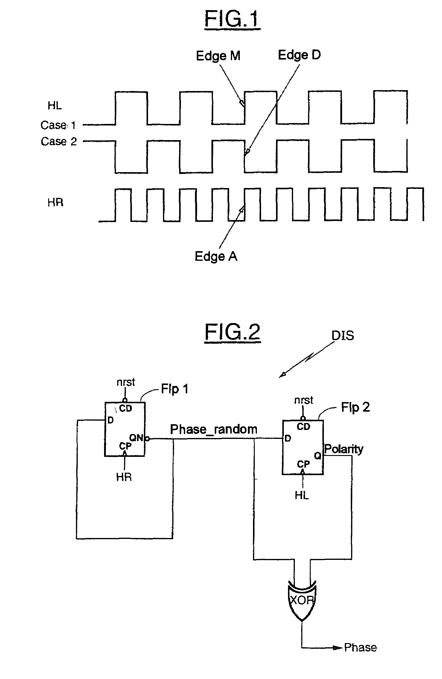
[0027 illustrates a first configuration where the two clocks are active on edges of like polarity such that a rising edge A of the fast clock HR corresponds to a rising edge M of the slow clock HL. Case 2 illustrates another configuration where the two clocks are active on edges of opposite polarities such that a rising edge A of the fast clock HR corresponds to a falling edge D of the slow clock HL.

[0028]In the example illustrated in FIG. 1, the two clock signals HL and HR are aligned, that is to say an edge of the clock signal Edge A, corresponds to an edge of the clock signal HL. However, during the embodiment of the circuit, the technology of the electronic components used may generate a shift between the edges of the clock signals.

[0029]Furthermore, the frequency of the clock signal HR is n times higher than the frequency of the clock signal HL. In this example, n=2, however, n may be any integer greater than 1.

[0030]Referring now to FIG. 2, a device DIS in accordance with the ...

case b

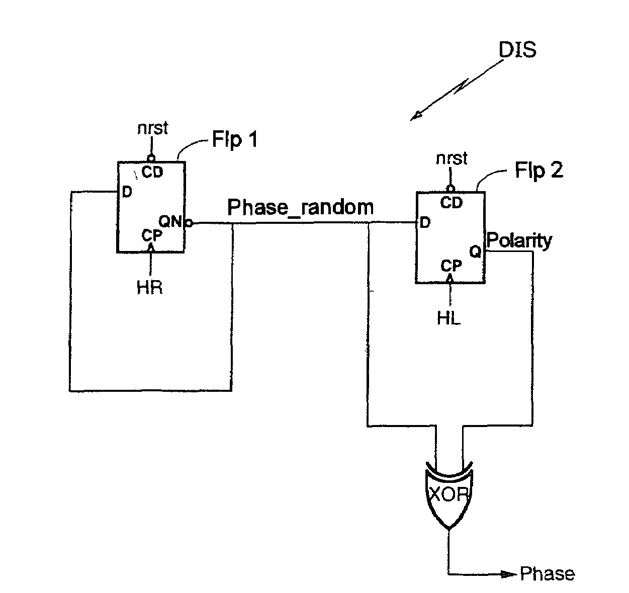
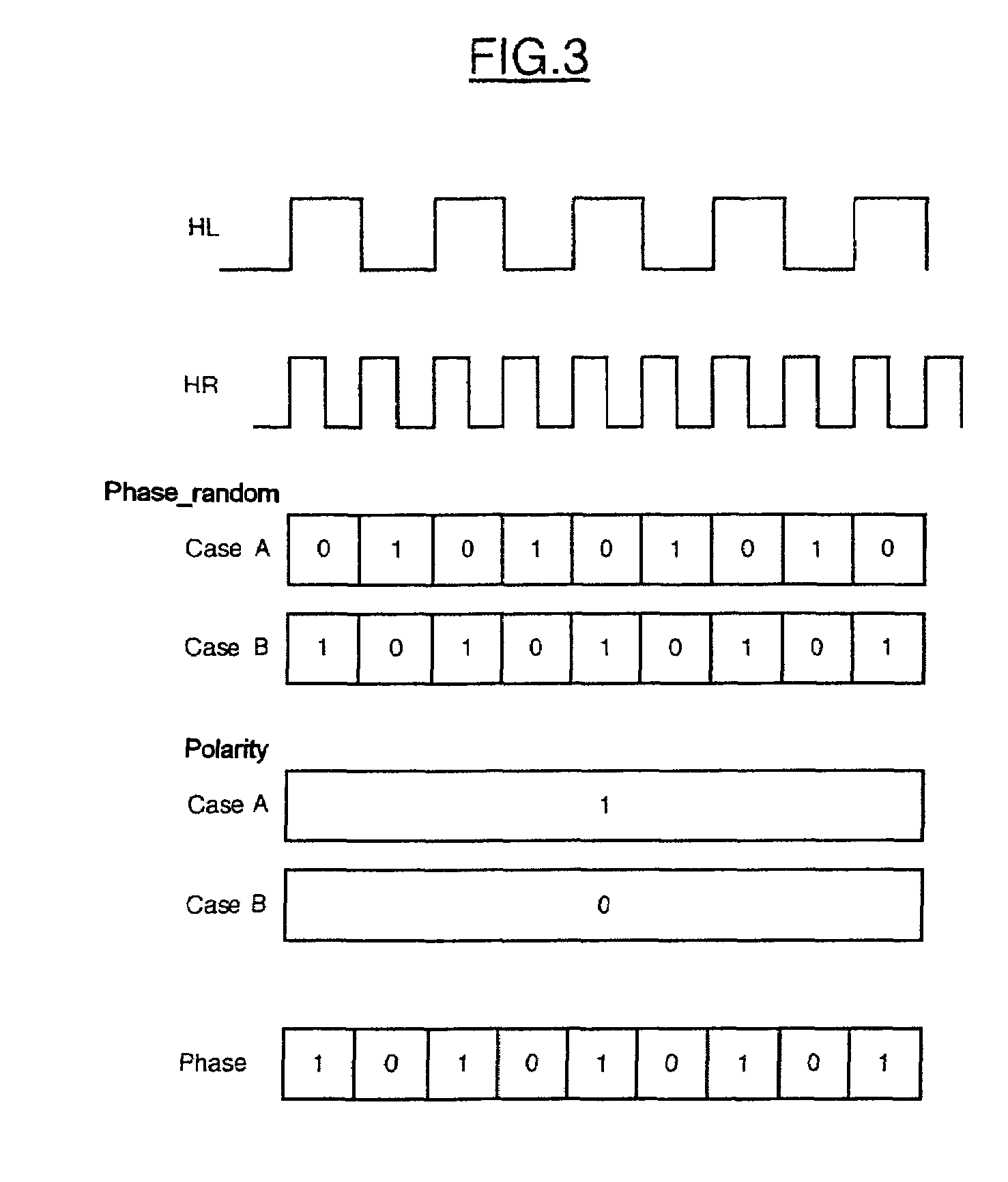
[0035 represents the situation where the first value taken by the signal Phase_random is “1”. In this case, the signal Phase_random takes successively the values “1” and then “0”, at the frequency of the fast clock signal HR.

[0036]Accordingly, as the values of the signal Phase_random follow case A or case B, the signal generated by the flip-flop Flp 2, Polarity, evolves according to two cases, case A or case B. The signal Polarity evolves according to case A if the signal Phase_random evolves also according to case A. In this case, the signal Polarity takes the value “1” regardless of the value of the signal Phase_random. The signal Polarity evolves according to case B if the signal Phase_random evolves according to case B. In this case, the signal Polarity takes the value “0” regardless of the value taken by the signal Phase_random.

[0037]The signal Phase is generated by the “EXCLUSIVE OR” logic gate, XOR. It is recalled that according to the truth table of the “EXCLUSIVE OR” functi...


PUM


Abstract

A device is for detecting a relative positioning of two clock signals including a fast clock signal and a slow clock signal. The fast clock frequency may be n times greater than a slow clock frequency, and n includes an integer greater than 1. The device includes a phase logic signal generator for generating a phase logic signal from the two clock signals by assigning a predetermined logic value to the phase logic signal when a rising edge of the fast clock signal matches a predetermined location of the slow clock signal.

Description

FIELD OF THE INVENTION[0001]The invention relates to the detection of the relative positioning of two signals, such as two clock signals.BACKGROUND OF THE INVENTION[0002]A known method of detecting the relative positioning of the clock edges of two clocks of different frequencies, proposes that the slow clock be sampled with the fast clock. In this way, it is possible to know during which cycle of the fast clock the change of level of the slow clock occurs.[0003]However, such an approach produces stability problems because one clock signal is sampled with the aid of a signal of another clock. Moreover, the approach of the prior art greatly complicates the management of the domain of the clock.SUMMARY OF THE INVENTION[0004]An object of the invention comprises ascertaining, during the transmission of data, the relative positioning of the clock signals of each domain in which the frequency of one of the clock signals is n times greater than the frequency of the other clock signal where...

Claims


Application Information

Patent Timeline
Patent Type & Authority Patents(United States)
IPC IPC(8): H03D3/24H03K19/096H03K5/26H04J3/04H04L7/00H04L7/02H04N7/62
CPCH03K5/26H04J3/047H04N21/4302H04L7/02H04N21/242H04L7/0012
Inventor CAUCHY, XAVIERSALVAIRE, ERICFORCE, CEDRIC
Owner STMICROELECTRONICS SRL
Learn More