Portable patient transfer system

a patient transfer and portable technology, applied in the field of incapacitated person handling, can solve the problems of inability to assist in the rescue of persons, large equipment, heavy equipment, etc., and achieve the effect of minimizing any slippage of the vest and improving the efficiency of lifting

Inactive Publication Date: 2009-12-08
3J CAPITAL
View PDF79 Cites 20 Cited by
  • Summary
  • Abstract
  • Description
  • Claims
  • Application Information

AI Technical Summary

Benefits of technology

[0019]In the patient lifting method of this invention, the caregiver places said vest portion on the patient's torso and secures said leg belt about the patient's legs just below the knees. The caregiver then pulls forwardly upon said front lifting handles while at the same time placing his knee between the patient's knees, and in contact with the leg belt. The leg belt thereby functions as a fulcrum which redirects the caregiver's pulling force to impart a lifting effect which pivots about the patient's knees to bring the patient to a standing position. Such manner of lifting enables the caregiver's spine to be erect, thereby transferring lifting force to his hips and legs. In a further embodiment, the patient is instructed to place downward force upon said forearm supports while gripping a forearm. Such action by the patient improves the efficiency of the lifting effect initiated by the caregiver, and minimizes any slippage of the vest.

Problems solved by technology

The aforesaid equipment, however, is large, cumbersome and expensive, and is intended primarily for use in hospitals and other health care facilities.
Such persons are usually incapacitated, exhausted or otherwise incapable of assisting in their rescue.
The lifting or manipulation of the victim can, however, be a formidable task for the caregiver.

Method used


Image

  • Portable patient transfer system
  • Portable patient transfer system
  • Portable patient transfer system

Examples


Embodiment Construction

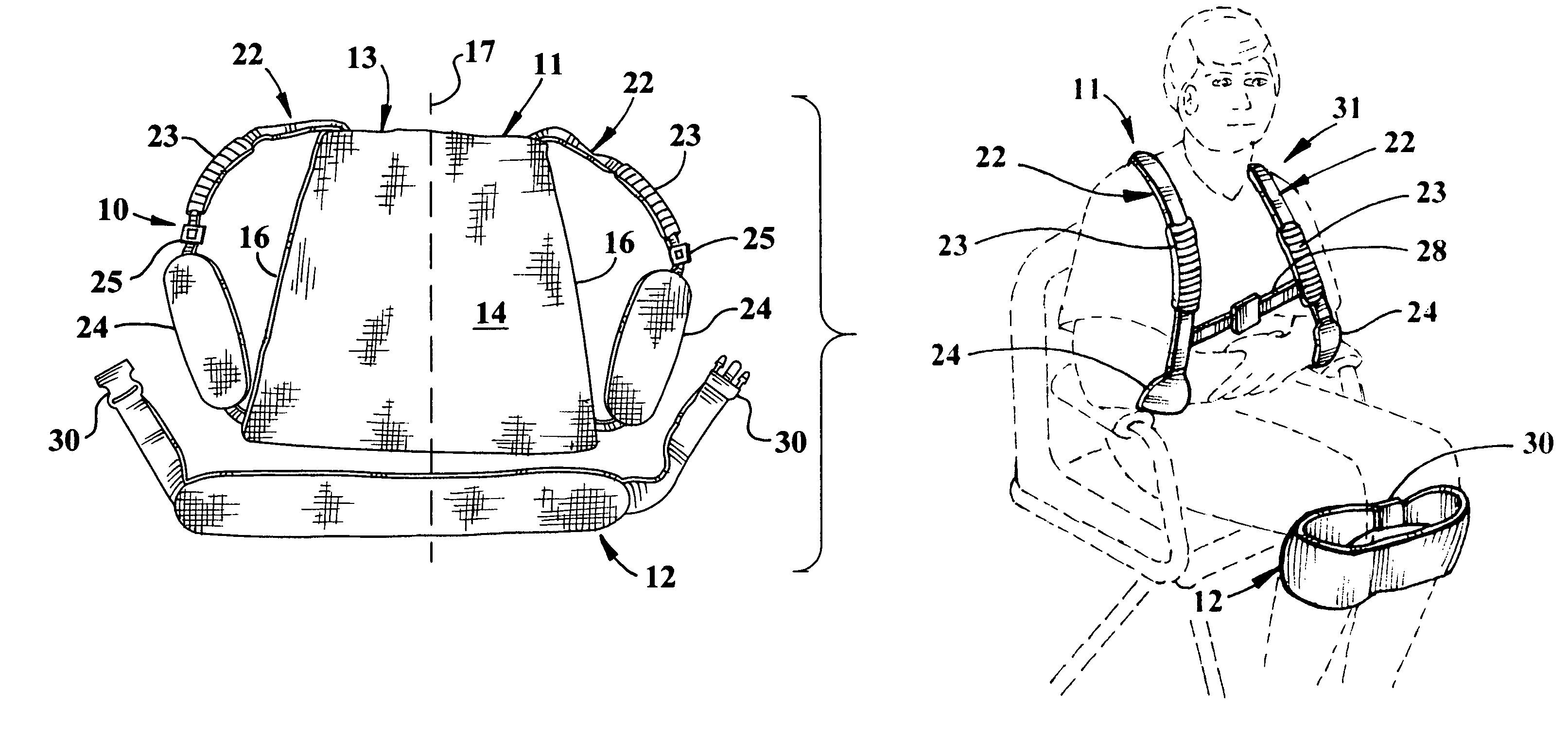
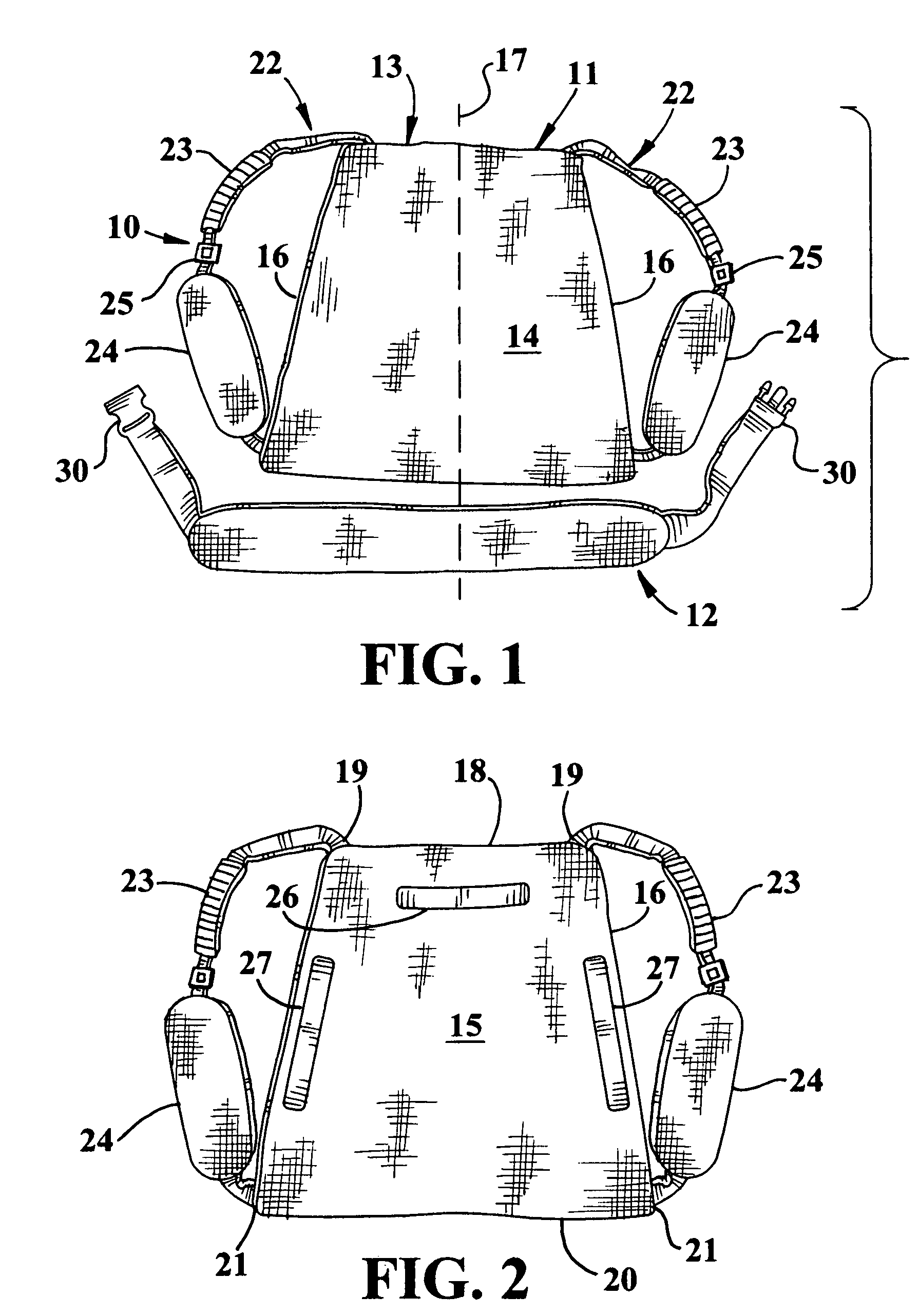
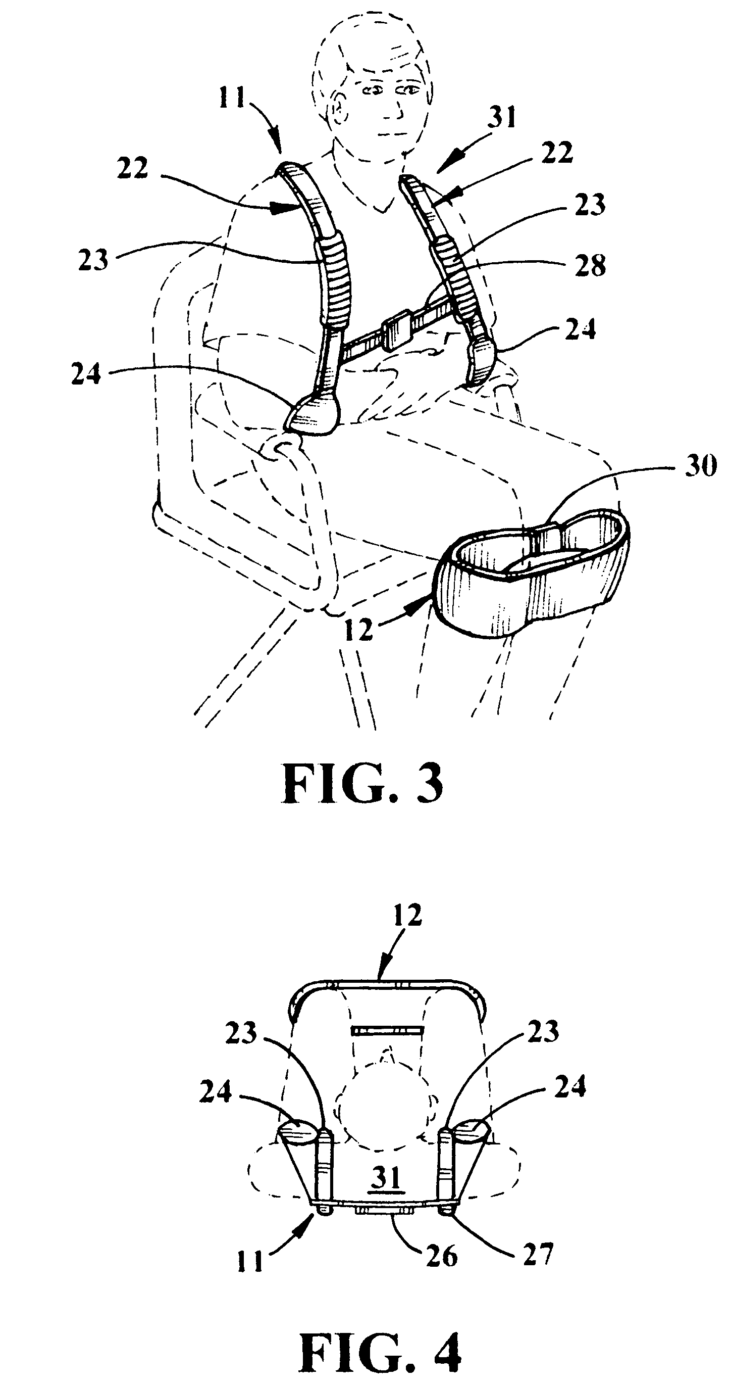
[0028]Referring now to FIGS. 1-7, an embodiment of the portable patient transfer system 10 of the present invention is shown comprised of vest component 11 and separate leg belt component 12.

[0029]Vest component 11 is comprised of a rear panel 13 fabricated of compliant strong material such as a heavy duty fabric tightly woven from high strength synthetic continuous filament yarns such as polypropylene, nylon and polyester. Panel 13 is bounded by front and rear surfaces 14 and 15, respectively, and has a substantially trapezoidal perimeter defined by two laterally opposed edges 16 upwardly convergent about a vertical center of symmetry 17, an upper horizontal edge 18 which meets with said laterally opposed edges to form upper corners 19, and a lower horizontal edge 20 of greater length than said upper edge, and meeting with said laterally opposed edges to form lower corners 21.

[0030]Shoulder strap means 22 are upwardly emergent from each upper corner 19, and downwardly descendent fo...


PUM


Abstract

A patient lifting system is provided having a vest component adjustably proportioned to fit upon the torso of a patient, and a leg belt component adapted to embrace the patient's legs just below the knees. A caregiver utilizes the lifting system by standing in front of the patient while pulling upon the vest and applying pushing force with his knee upon the leg belt. Such action causes the leg belt to act as a fulcrum which redirects the pulling force upwardly to lift the patient.

Description

RELATED APPLICATIONS[0001]This invention is the subject of a Provisional Application filed Sep. 8, 2008 as Ser. No. 61 / 191,325.BACKGROUND OF THE INVENTION[0002]1. Field of the Invention[0003]This invention concerns the handling of incapacitated persons, and more particularly relates to a method and apparatus for lifting and moving an injured or invalid person without the aid of heavy duty equipment.[0004]2. Description of the Prior Art[0005]Equipment for lifting patients from a seated position such as a wheelchair to a standing position is well known for use in hospitals. Embodiments of such equipment are described, for example, in U.S. Pat. Nos. 7,356,858 and 5,878,450. Related apparatus for lifting, supporting and transporting a patient is disclosed in U.S. Pat. No. 6,289,534 and elsewhere. The aforesaid equipment, however, is large, cumbersome and expensive, and is intended primarily for use in hospitals and other health care facilities.[0006]It is often necessary to rescue and r...

Claims


Application Information

Patent Timeline
Patent Type & Authority Patents(United States)
IPC IPC(8): A61G7/10A61G7/14
CPCA61G7/1011A61G7/1096A61G7/1051A61G7/1038
Inventor MCKINNEY, THOMAS WADE
Owner 3J CAPITAL
Why Eureka
Try Eureka