Accumulator for subsea equipment

a technology for accumulators and subsea equipment, applied in the direction of fluid couplings, sealing/packing, borehole/well accessories, etc., can solve the problems of significant pressure drop, affecting the operation, and essentially unusable remaining fluid in the conventional accumulator, so as to achieve maximum gauge pressure and maintain an operating safety margin.

Active Publication Date: 2009-12-08
ONESUBSEA IP UK LTD
View PDF28 Cites 35 Cited by
  • Summary
  • Abstract
  • Description
  • Claims
  • Application Information

AI Technical Summary

Benefits of technology

[0011]Apparatus in accordance with the present invention also comprises a movable piston which is located within the housing proximate the second end of the housing. The movable piston has first and second ends with first and second cross-sectional areas, respectively. The piston is movable between a first position and a second position within the housing, and the second end of the housing includes a port to permit ambient pressure to impinge on the first end of the piston. The second end of the piston is in contact with the third chamber. When the force imparted to the first end of the piston by the hydrostatic pressure exceeds the force imparted to the second end of the piston by the sum of the hydrostatic pressure and the pressure of the fluid in the second chamber, the piston will begin to move, thereby expelling fluid from the second chamber of the accumulator. The cross-sectional areas of the first and second ends of the piston may be selected so as to maximize the gauge pressure of the second chamber at which the piston will start to move, while at the same time in maintaining an operating safety margin.

Problems solved by technology

If the piece of equipment or the device is located a considerable distance from the pump, a significant pressure drop can occur in the hydraulic conduit or pipe which is conveying the fluid from the pump to operate the device.
Consequently, operation may be delayed until such a time as the pressure can build up with the fluid being pumped through the hydraulic line.
Once the conventional accumulator begins to displace fluid, the pressure of the non-compressible fluid decreases and cannot overcome the hydrostatic pressure thus causing the remaining fluid in the conventional accumulator to become essentially unusable.
In a deep subsea well, the gas precharge pressure may be higher than the hydraulic fluid pressure rendering the accumulator useless when testing the hydraulic circuit at the surface.
A conventional accumulator has the further shortcoming that it cannot be used at several different depths and unless it is used at the depth for which it is configured, it may still have an amount of unusable hydraulic fluid.

Method used


Image

  • Accumulator for subsea equipment
  • Accumulator for subsea equipment
  • Accumulator for subsea equipment

Examples


Embodiment Construction

[0021]It will be appreciated that the present invention may take many forms and embodiments. In the following description, some embodiments of the invention are described and numerous details are set forth to provide an understanding of the present invention. Those skilled in the art will appreciate, however, that the present invention may be practiced without those details and that numerous variations and modifications from the described embodiments may be possible. The following description is thus intended to illustrate and not to limit the present invention.

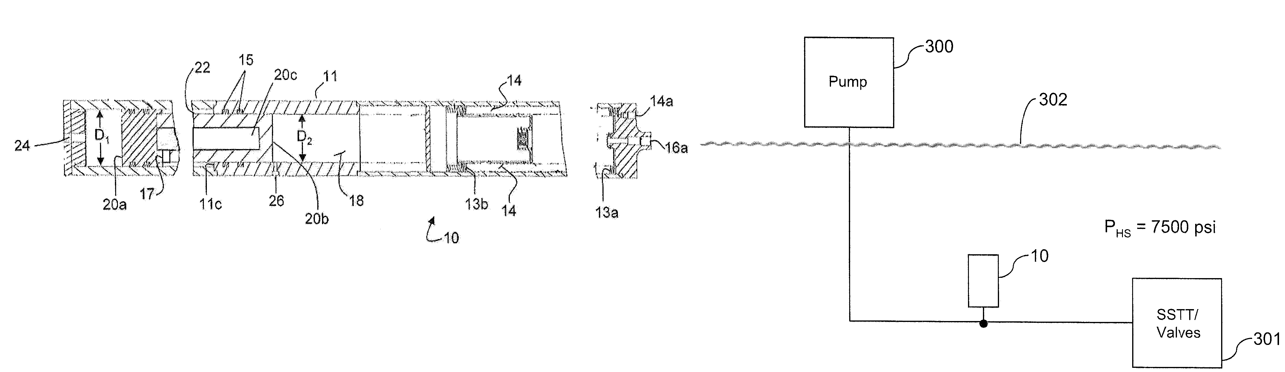
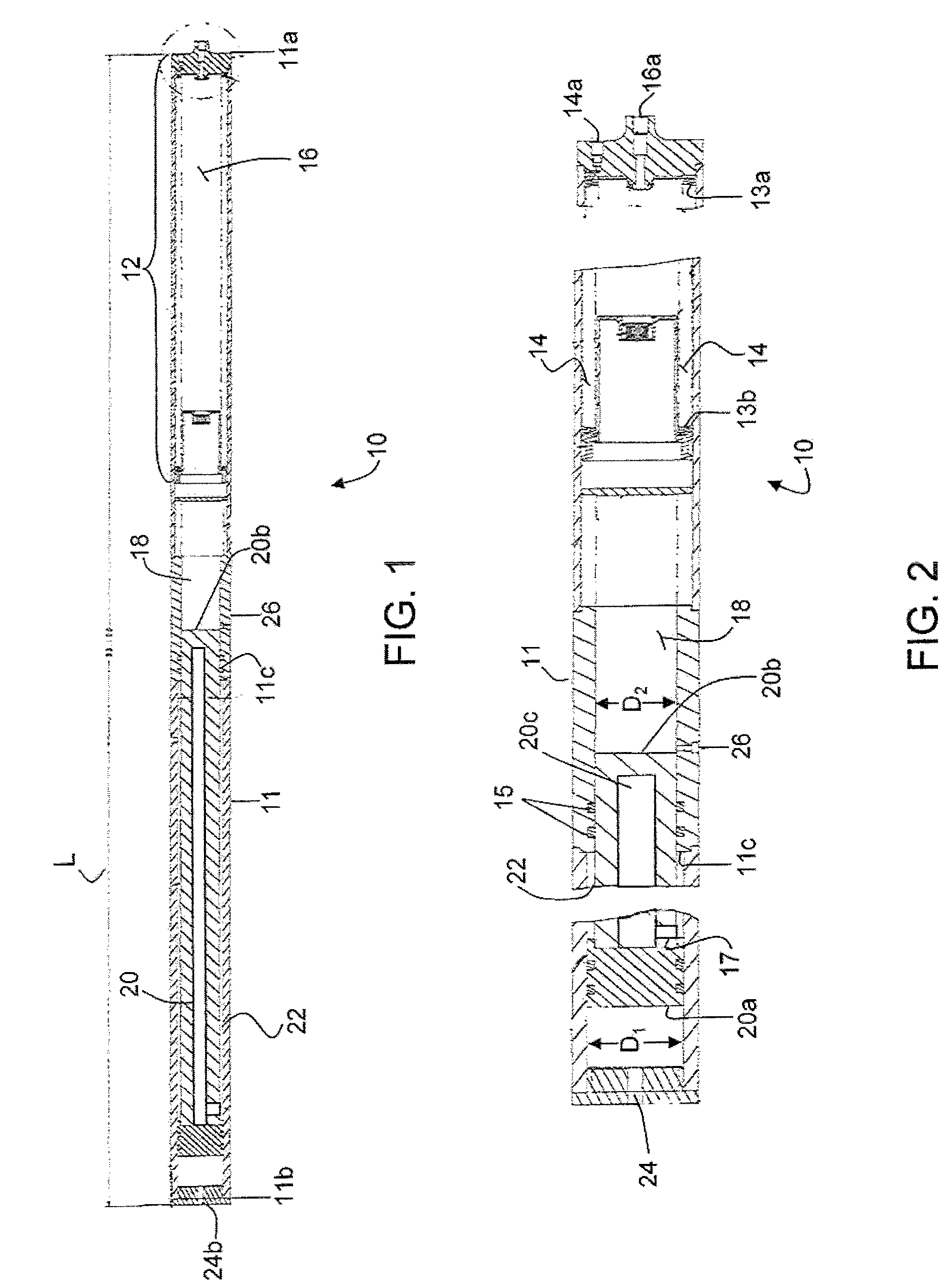
[0022]With reference to both FIGS. 1 and 2, apparatus 10 in accordance with the present invention comprises housing 11, which is a generally tubular-shaped member having two ends 11a and 11b. An accumulator 12 is located within the housing 11 proximate the first end 11a thereof. The accumulator 12 comprises a first chamber 14 for receiving a pressurized gas at a first pressure. The pressurized gas may, for example, be injecte...


PUM


Abstract

Pressure-balanced accumulator apparatus for use in subsea operations is disclosed which comprises a housing and an accumulator within the housing at the first end of the housing. The accumulator has first and second chambers that are hermetically sealed from one another, with a pressurized gas in the first chamber and a pressurized fluid in the second chamber. A third chamber in the housing abuts the accumulator and contains silicon oil fluid. A movable piston is located within the housing proximate the second end of the housing. Ambient pressure is communicated to one end of the piston, and ambient pressure plus the pressure in the second chamber is communicated to the second end of the piston. The cross-sectional areas of the two ends of the piston are selected to optimize the pressure at which the piston begins to expel fluid from the second chamber.

Description

BACKGROUND OF THE INVENTION[0001]1. Field of the Invention[0002]The present invention relates to an accumulator for use in controlling an in-riser or open water intervention system such as a subsea stack of Subsea Test Tree (“SSTT”) and the valves associated therewith.[0003]2. Description of the Prior Art[0004]Accumulators are devices that provide a reserve of hydraulic fluid under pressure and are used in conventional hydraulically-driven systems where hydraulic fluid under pressure operates a piece of equipment or a device. The hydraulic fluid is pressurized by a pump that maintains the high pressure required.[0005]If the piece of equipment or the device is located a considerable distance from the pump, a significant pressure drop can occur in the hydraulic conduit or pipe which is conveying the fluid from the pump to operate the device. Therefore, the flow may be such that the pressure level at the device is below the pressure required to operate the device. Consequently, operati...

Claims


Application Information

Patent Timeline
Patent Type & Authority Patents(United States)
IPC IPC(8): E21B29/12
CPCE21B33/038E21B33/0355
Inventor LEONARDI, TAUNASCRANTON, JOSEPH D.
Owner ONESUBSEA IP UK LTD
Why Eureka
Try Eureka