Adhesion device by holding low pressure

a technology of adhesion device and low pressure, which is applied in the direction of shaving accessories, machine supports, other domestic objects, etc., can solve the problems of difficult to fix the adhesion device (b>10/b>) on a relatively rough surface like a dashboard, and achieves strong and more effective adhesion force and effective adhesion

Inactive Publication Date: 2009-12-08
SONG SOON YOUNG
View PDF6 Cites 56 Cited by
  • Summary
  • Abstract
  • Description
  • Claims
  • Application Information

AI Technical Summary

Benefits of technology

[0005]The present invention has been made to solve these problems and it is an object of the present invention to provide an adhesion device capable of providing and maintaining a stronger and more effective adhesion force by maintaining the pressure between the adhesion surface and the adhesion device lower than the atmospheric pressure or close to vacuum and of offering an effective adhesion to a relatively rough or uneven adhesion surface like a dashboard of a car.

Problems solved by technology

However, the conventional adhesion device (10) is disadvantageous in that, since air exists in the inner space between the suction plane (13) and the adhesion surface prior to attaching the adhesion device (10) as seen in FIG. 1, it is difficult to attain a strong adhesion force because it is not easy to lower the pressure inside the inner space close to vacuum by expanding the inner space.
Further, the conventional adhesion device (10) is attached only on a smooth surface like glass and it is difficult to fix the adhesion device (10) on a relatively rough surface like a dashboard.
Particularly, it is not easy to attach the adhesion device on a curved, not flat, adhesion surface.
The windowpane or dashboard of a car is not completely flat but curved and it is almost impossible to firmly attach the conventional adhesion device on such a curved surface.

Method used


Image

  • Adhesion device by holding low pressure
  • Adhesion device by holding low pressure
  • Adhesion device by holding low pressure

Examples


Embodiment Construction

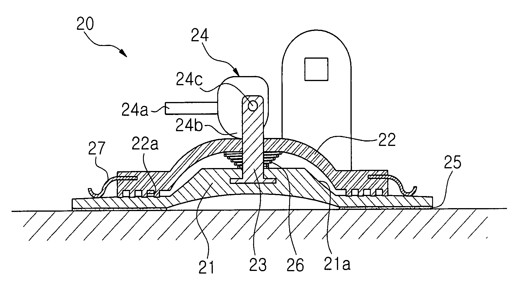
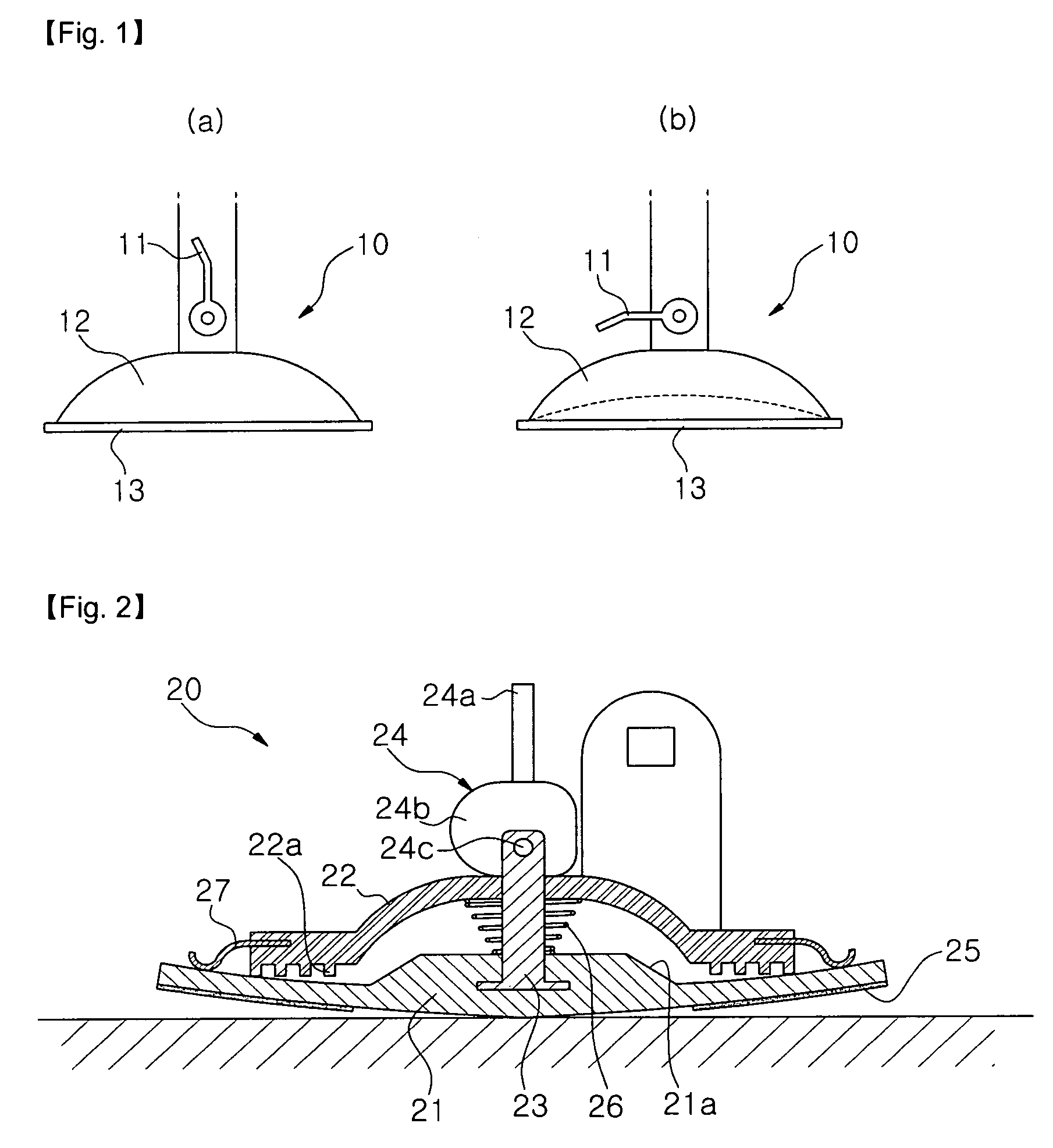
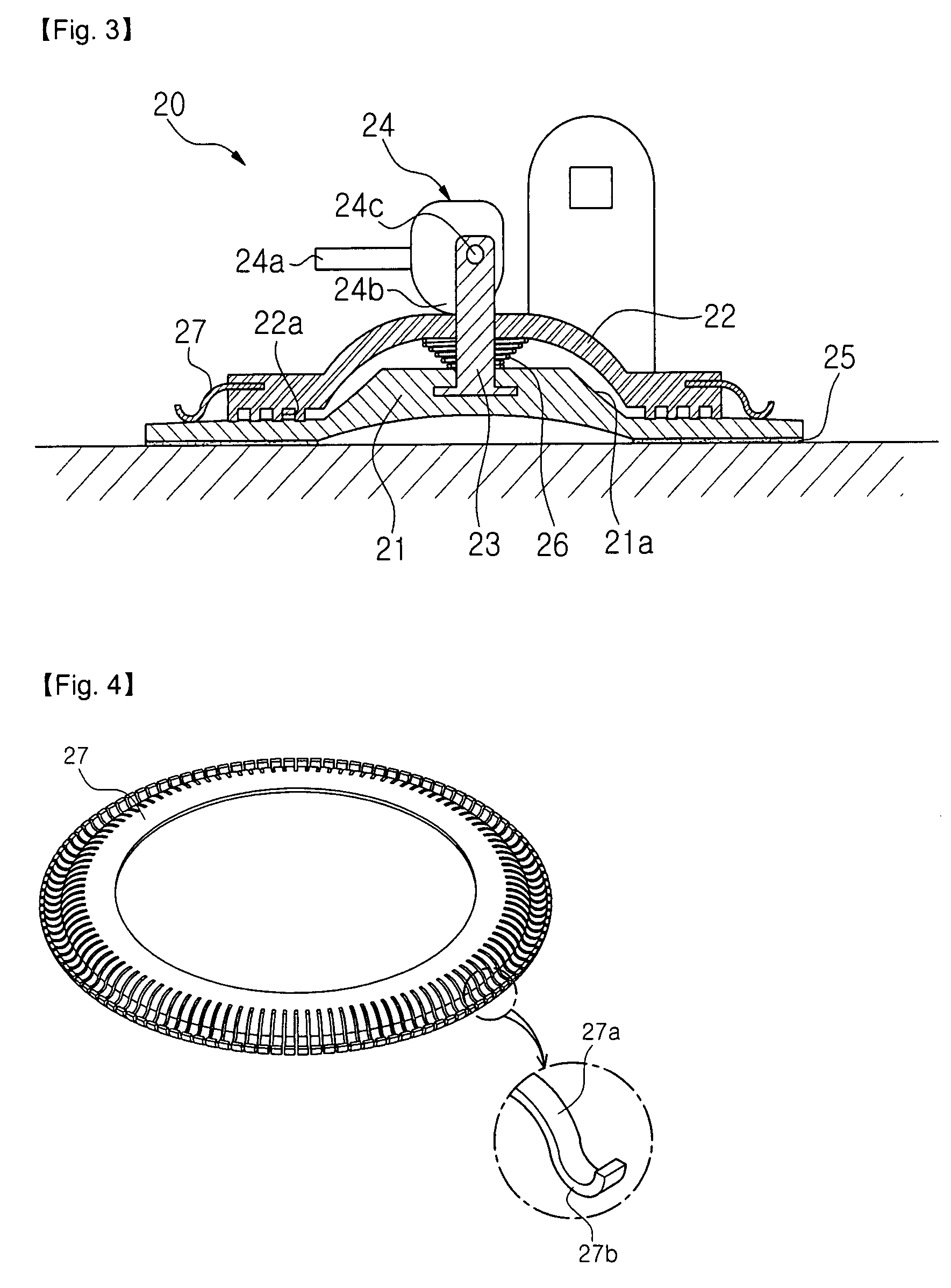
[0012]Now, the adhesion device of the present invention is described in detail referring to FIGS. 2 to 8.

[0013]FIG. 2 is a cross-sectional side view of the adhesion device according to the present invention before being attached to an adhesion surface. The adhesion device comprises a pad (21), a center element (23), a housing (22) and an adhesion controller (24). The pad (21) has a bottom surface which is attached to the adhesion surface and a top surface connected with the center element (23). The center element (23) is fixed upright at the center of the top surface of the pad (21). The housing (22) has a round semi-spherical shape and has a hole through which the center element (23) passes at the center. The adhesion controller (24) comprises a lever (24a) and a press (24b) and is capable of rotating around an axis (24c) as connected to the center element (23) at the top end. In the adhesion device according to the present invention, the housing (22) is located at the top surface ...


PUM


Abstract

Provided is an adhesion device used to cradle a car navigation system, a mobile phone, etc. The adhesion device according to the present invention comprises a pad (21) having a bottom surface attached to an adhesion surface, a center element (23) fixed upright at the center of the top surface of the pad (21), a housing (22) placed on the top surface of the pad (21) and having a hole through which the center element (23) passes, a ring-shaped leaf spring (27) which is equipped at the outer circumference of the housing (22) and presses the outer circumference of the top surface of the pad (21) and an adhesion controller (24) connected with the top end of the center element (23) by an axis (24c). The adhesion controller (24) comprises a lever (24a) and a press (24b). When the lever (24a) is rotated around the axis (24c), the press (24b) presses down the top surface of the housing (22) and the center of the pad (21) connected with the center element (23) is moved upward, resulting in an expansion of the space between the pad (21) and the adhesion surface and a pressure lower than the atmospheric pressure.

Description

TECHNICAL FIELD[0001]The present invention relates to an adhesion device used to firmly attach an article on a surface. More particularly, it relates to an adhesion device to cradle a navigation system, a monitor, and so forth.BACKGROUND ART[0002]Recently, a lot of car drivers use mobile phones, navigation systems, monitors, etc. by attaching them on the front windowpane, dashboard, etc. An adhesion device as illustrated in FIG. 1 is used to attach them. FIG. 1a shows the status before the adhesion device is attached on an adhesion surface and FIG. 1b shows the status after the adhesion device has been attached. Referring to FIG. 1a, the adhesion device (10) comprises a housing (12) and a suction plane (13). Above the housing (12) is a support connector for cradling a mobile phone, a navigation system, and so forth. The support connector is equipped with a lever (11). At the center of the suction plane (13), the suction plane (13) is connected with the lever (11) by a center element...

Claims


Application Information

Patent Timeline
Patent Type & Authority Patents(United States)
IPC IPC(8): A45D42/14F16B47/00
CPCF16B47/003F16B47/00
Inventor SONG, SOON YOUNG
Owner SONG SOON YOUNG
Why Eureka
Try Eureka