Exchangeable tool

a tool and tool body technology, applied in the field of exchangeable tools, can solve the problems of adverse effect on the productive time of the machine, and achieve the effect of preventing the possibility of rotation and preventing the rotation accordingly

Active Publication Date: 2009-12-15
WILA
View PDF43 Cites 14 Cited by
  • Summary
  • Abstract
  • Description
  • Claims
  • Application Information

AI Technical Summary

Benefits of technology

[0014]Preferably the cavity is cylindrical with at least a rib extending through the cavity. This rib prevents the possible rotation between the tool and the manipulator.
[0015]In another preferred embodiment two parallel ribs are arranged at the mouth opening of the cavity. These two ribs provide a further locking of the angular position of the tool in relation to the manipulator and prevents accordingly rotation.
[0016]In yet another embodiment of the tool according to the invention the cavity has a non-circular cross-section perpendicular to the insertion axis, the cross-section being for example square or elliptical. This enables insertion of a corresponding manipulator into the tool, and prevents rotation of the tool relative to the manipulator.

Problems solved by technology

This would have an adverse effect on the productive time of the machine.

Method used


Image

  • Exchangeable tool
  • Exchangeable tool
  • Exchangeable tool

Examples


Embodiment Construction

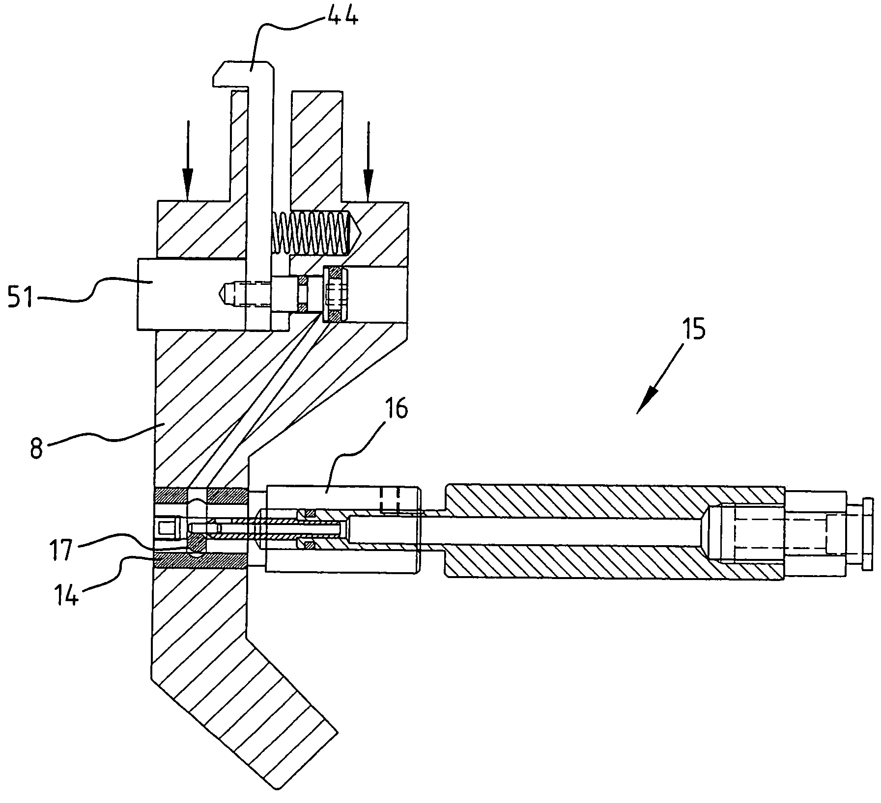
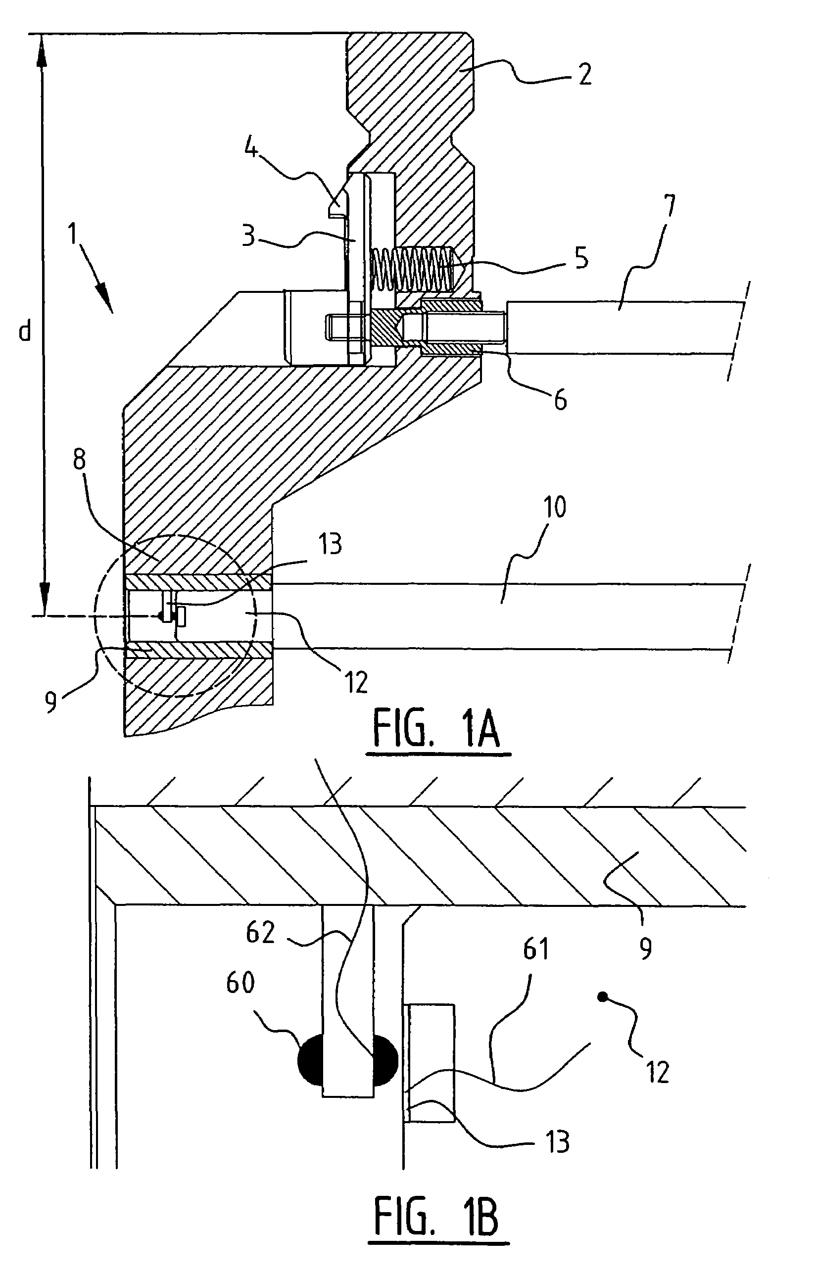
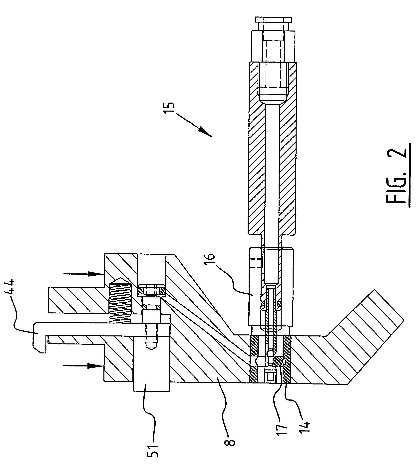
[0041]FIG. 1A shows a tool 1 according to the invention. This tool 1 has a receiving end 2, which is suitable to be inserted into a receiving structure of a machine. In this receiving end 2 a safety device 3 is arranged having a safety member 4, which protrudes into a cavity of the receiving structure and prevents the tool from falling out of the receiving structure. Only by retracting the safety member 4 into the receiving end 2, the tool 1 can be taken out from the receiving structure.

[0042]The safety device 3 is urged by spring 5. The shown position of the safety device 3 is limited by a guide 6. In this guide 6 a manipulator 7 can be inserted to pull the safety device 3 into the receiving end 2 and to retract the safety member 4 enabling the taking out of the tool 1 from the receiving structure.

[0043]In the tool body 8 a bush 9 is arranged, which provides the connecting means for the second manipulator 10 of a robot arm. This bush 9 is provided with thread, such that the manipul...


PUM

PropertyMeasurementUnit
forceaaaaaaaaaa
distanceaaaaaaaaaa
sizesaaaaaaaaaa

Abstract

The invention relates to an exchangeable tool having a tool body with a receiving end for holding the tool in a receiving structure, wherein a connector is arranged in the tool body for providing a substantially non-rotatable connection with a manipulator for manipulating the tool into and out from the receiving structure,
    • to a combination of such tool with a manipulator for manipulating the tool into and out from a receiving structure,
    • and to a method for manipulating such tool into and out from a receiving structure.

Description

BACKGROUND OF THE INVENTION[0001]1) Field of the Invention[0002]The invention relates to an exchangeable tool having a tool body with a receiving end for holding the tool in a receiving structure.[0003]2) Description of the Prior Art[0004]Such a tool is, for example, known from the European Patent Publication No. 0 494 714.SUMMARY OF THE INVENTION[0005]When automating the exchange of tools, a manipulator, such as a robot arm is used to take the tools and transport them from the machine, in which the tools are used, to a storage, and vice versa. When manipulating the tools with a manipulator it is beneficial that the tools will not rotate in relation to the manipulator. This is necessary to ensure the control logic to know the exact position of the tool at the end of the manipulator arm, such that the tool can be reliably inserted into the respective machine or into the storage. If the tool would be able to shift or rotate uncontrolled, the manipulator would need to re-orientate the ...

Claims


Application Information

Patent Timeline
Patent Type & Authority Patents(United States)
IPC IPC(8): B23Q3/155B21D37/00B21D37/04
CPCB23Q3/1556B25J15/04Y10T483/11Y10T483/1729Y10S483/901B21D5/0254
Inventor ROUWELER, FRANCISCUS WILHELMUSBRUGGINK, GERRIT
Owner WILA
Why Eureka
Try Eureka