Moisture removal apparatus and method

a technology of air filter and apparatus, which is applied in the direction of filtration separation, combustion-air/fuel-air treatment, and separation processes, etc., can solve the problems of large footprint, large known filter system, and ineffectiveness of known filter system, etc., to improve the moisture removal effect of filter system, reduce the size of the housing package, and improve the effect of moisture removal

Inactive Publication Date: 2009-12-15
BHA ALTAIR
View PDF11 Cites 33 Cited by
  • Summary
  • Abstract
  • Description
  • Claims
  • Application Information

AI Technical Summary

Benefits of technology

[0005]The invention offers an improved moisture removal for filter systems. The improvements include a relatively smaller housing package, consistent moisture removal over time by a filter with simple and reliable mounting structure.

Problems solved by technology

Such known gas turbine filter systems may be rather large.
That is, they occupy a relatively large “footprint” adjacent to the gas turbine which may be undesirable in some applications.
Such known filter systems may also not be as effective as desired and have other disadvantages, for example leakage around mounting structure.

Method used


Image

  • Moisture removal apparatus and method
  • Moisture removal apparatus and method
  • Moisture removal apparatus and method

Examples


Embodiment Construction

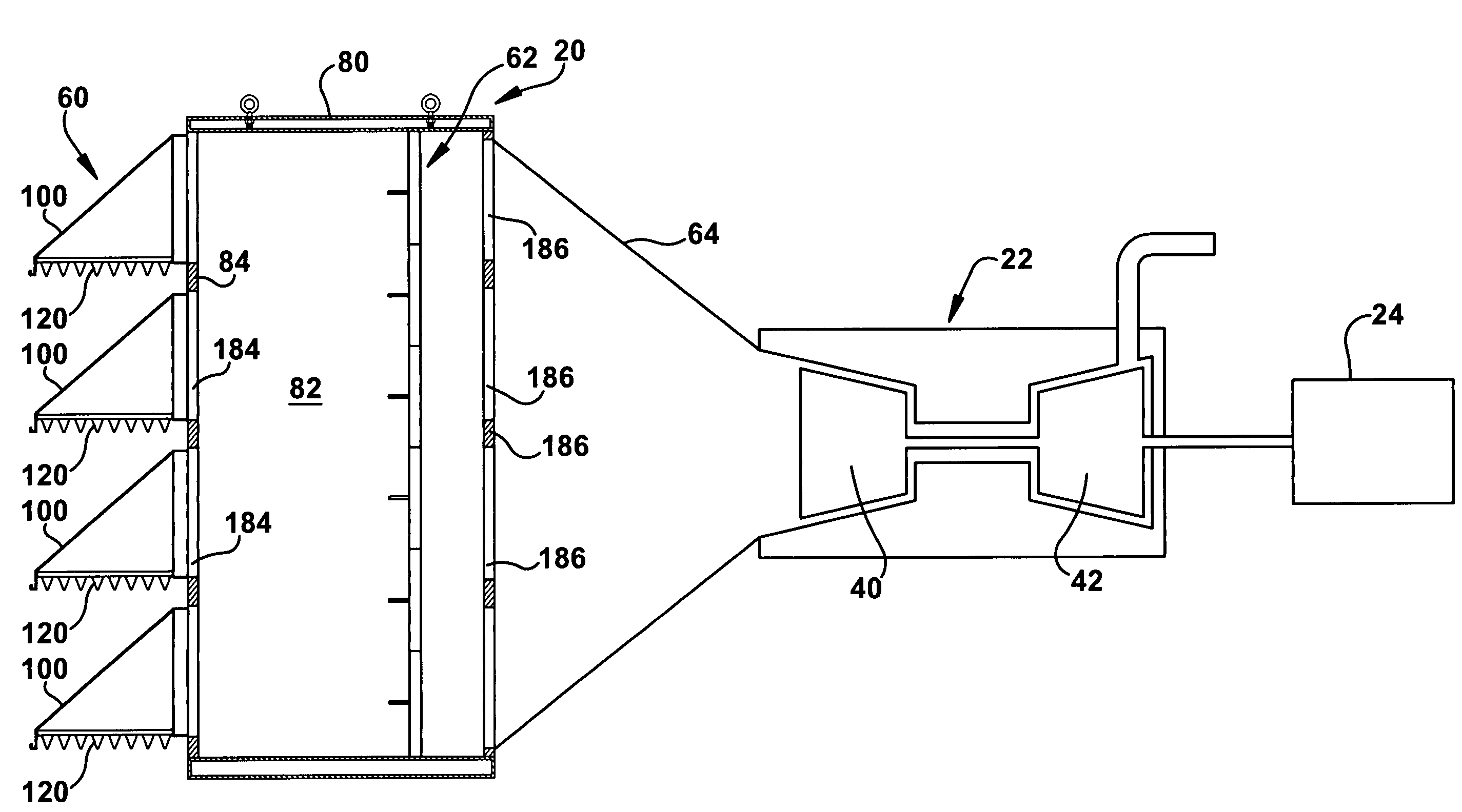
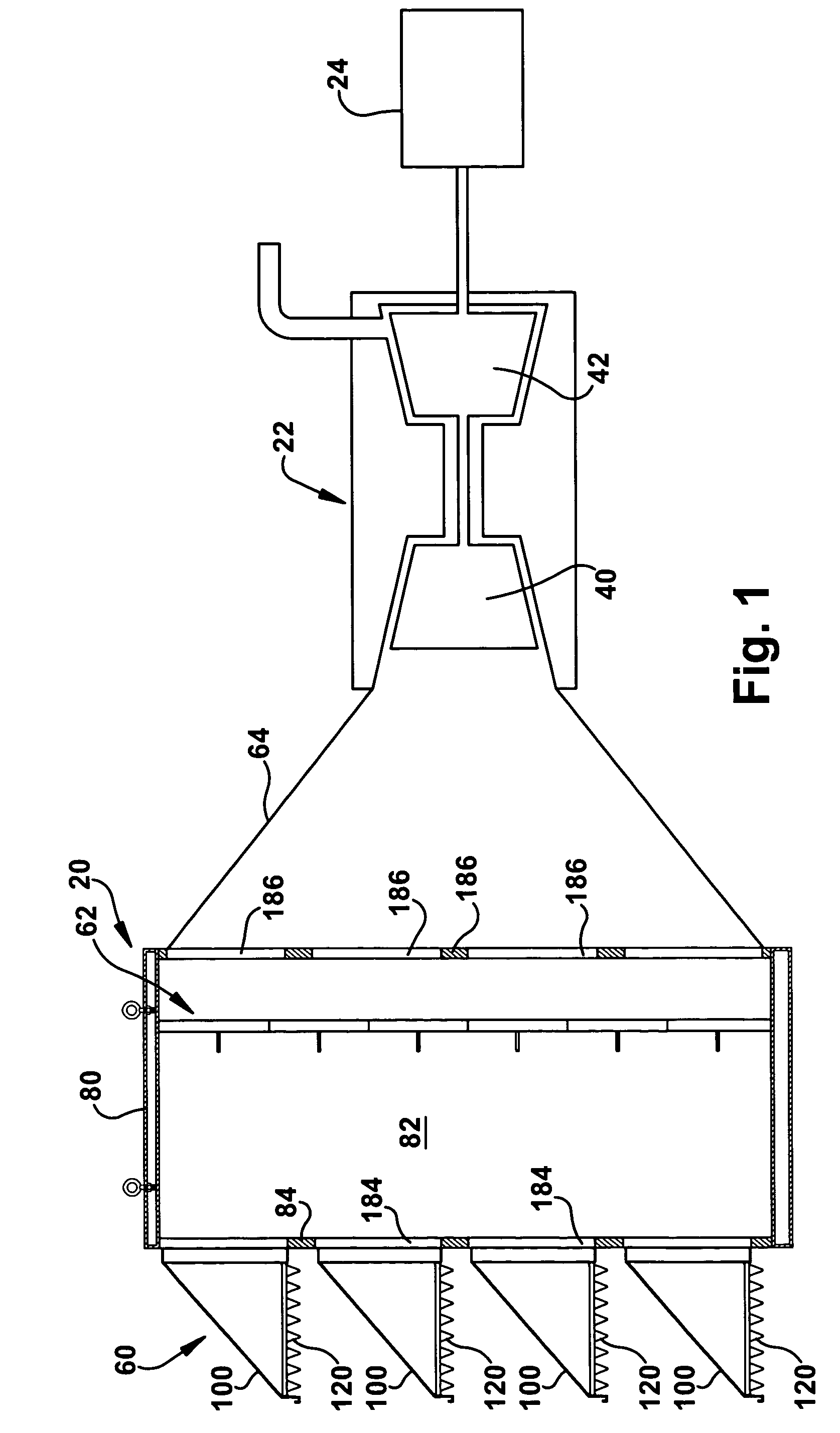
[0015]A filter system 20 constructed according to one aspect of the invention for filtering inlet air of a gas turbine 22 is illustrated in FIG. 1. The gas turbine 22 can be used for any desired purpose, such as powering an electrical generator 24. The gas turbine 22 uses a relatively large quantity of air that is directed to a compressor portion 40, gets ignited and where expanding gases ultimately drive a turbine portion 42. The large quantity of inlet air must be filtered of particulates, salt and moisture in order to prevent damage and accelerated wear to components of the gas turbine 22.

[0016]Various aspects of the invention are described with respect to an inlet system for a gas turbine 22. It will be appreciated that the aspects of the invention are also applicable to a variety of other applications that are prone to damage by moisture and particulates. For example, the various aspects of the present invention are applicable to applications such as internal combustion engine ...


PUM

PropertyMeasurementUnit
thicknessaaaaaaaaaa
acute angleaaaaaaaaaa
hydrophobicaaaaaaaaaa

Abstract

A method of removing moisture from inlet air flowing to a gas turbine. The method comprises the steps of providing a housing for supporting a primary air filter. The housing is operably connected with the gas turbine. A hood connected with the housing is provided. The hood has a surface disposed at an acute angle relative to horizontal. Inlet air flow is directed into a preliminary filter supported above the hood and extending in a downward direction. The preliminary filter comprises media capable of separating moisture from the inlet air flowing through the preliminary filter at an exterior portion of the preliminary filter. Separated moisture agglomerates into a drop incapable of being carried by the flow of inlet air so the drop falls onto the hood to be directed out of the flow of inlet air.

Description

BACKGROUND OF THE INVENTION[0001]The present invention relates generally to an air filter system. In particular, the present invention relates to structure and method for removing moisture from gas turbine inlet air.[0002]Filter systems for gas turbine inlet air are known. One such known system includes a housing defining chamber. The chamber has an air inlet side and an air outlet side separated by an array of filters for removing particulates from the inlet air flow. Air enters the chamber through a plurality of vertically spaced inlet hoods positioned along the air inlet side. The inlet hoods are configured such that air entering the inlet hoods is first directed in an upward direction and then deflected by deflector plates in a downward direction. Air flow contact with the deflector plates causes some particulate material and moisture from the moving air to separate from the air flow and settle or accumulate on the inlet hoods or in the bottom of the chamber.[0003]Another known ...

Claims


Application Information

Patent Timeline
Patent Type & Authority Patents(United States)
IPC IPC(8): B01D46/00
CPCF02C7/055B01D46/0031Y10S55/17Y10S55/18B01D35/30B01D46/00B01D46/52F02C7/04F02C7/05F01D25/00
Inventor SINGH, AVNIT
Owner BHA ALTAIR
Why Eureka
Try Eureka