Electrical connection box

a technology of connecting box and cable, which is applied in the direction of electrical apparatus casing/cabinet/drawer, coupling device connection, inorganic insulator, etc., can solve the problem of short circuit between the signal terminals, and achieve the effect of preventing short circuit between the connecter terminals disposed on the ceiling portion

Active Publication Date: 2009-12-15
AUTONETWORKS TECH LTD +2
View PDF14 Cites 18 Cited by
  • Summary
  • Abstract
  • Description
  • Claims
  • Application Information

AI Technical Summary

Benefits of technology

[0019]According to the construction of the present invention, water having intruded into the circuit casing drops onto the waterproof portion and thereby is prevented from reaching the ceiling portion of the h

Problems solved by technology

This could result in short-circuiting among the signal terminals disposed on the upper surface of the hood portion.
Because this case includes sig

Method used


Image

  • Electrical connection box
  • Electrical connection box
  • Electrical connection box

Examples


first embodiment

[0045]A first embodiment according to the present invention will be hereinafter explained with reference to FIGS. 1 through 5.

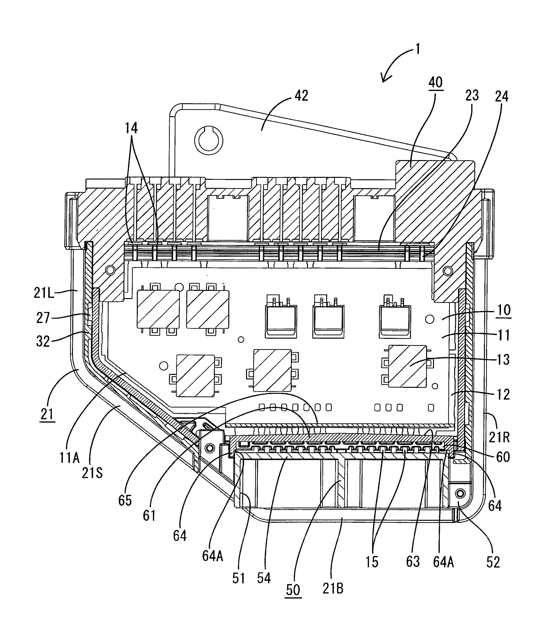
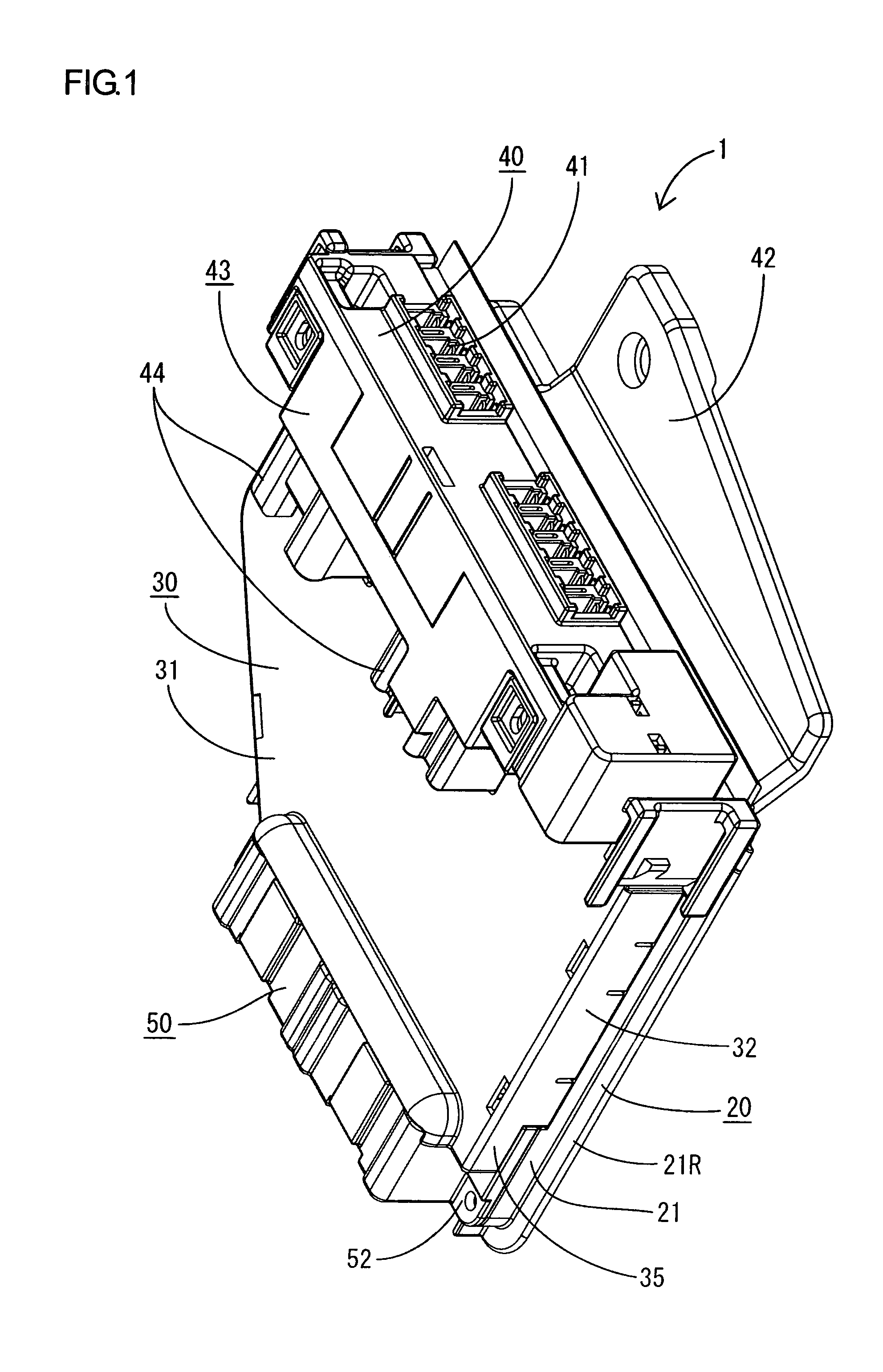
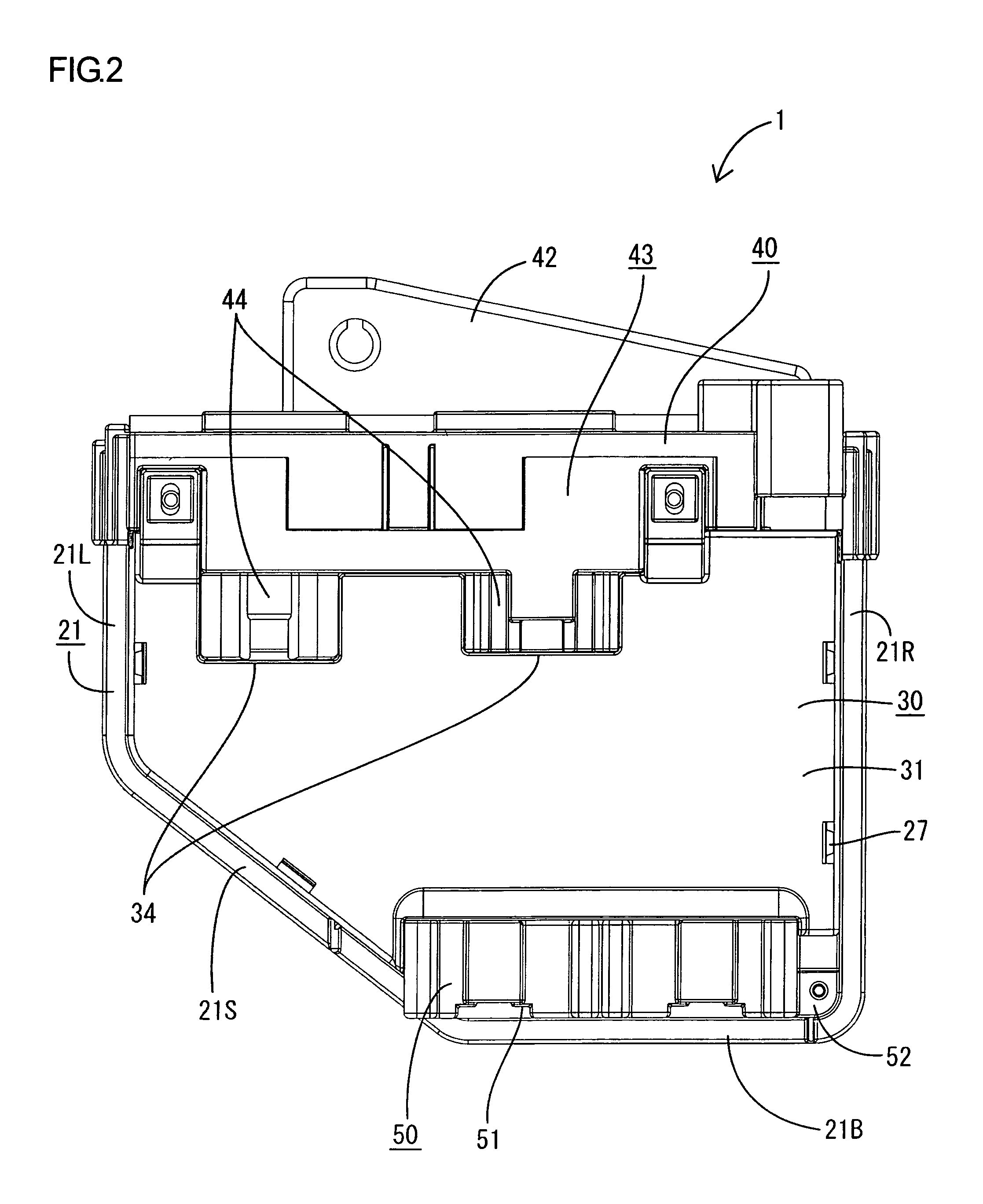
[0046]FIG. 1 is an appearance perspective view of an electrical connection box 1 according to the first embodiment. FIG. 2 is a top view of the electrical connection box 1 according to the first embodiment. FIG. 3 is a bottom view of the electrical connection box 1 according to the first embodiment. FIG. 4 is a side sectional view of the electrical connection box 1 according to the first embodiment. FIG. 5 is a horizontal sectional view of the electrical connection box 1 according to the first embodiment.

[0047]In the electrical connection box 1, a circuit structure 10 including a circuit board 11 and a bus bar 12 is housed vertically in a casing 20 comprising a frame body 21 and a radiator panel 22, and the front side thereof is covered with a cover 30. The casing 20 and the cover 30 correspond to a circuit casing of the present invention.

[0048]Hereinafter, e...

second embodiment

[0077]Hereinafter, a second embodiment of the present invention will be explained with reference to FIGS. 6 and 7.

[0078]FIGS. 6 and 7 show the side and horizontal sectional views of an electrical connection box 101 according to the second embodiment, respectively.

[0079]In the electrical connection box 101 according to the present embodiment, similarly to the first embodiment, a circuit structure 10 including a circuit board 11 and a bus bar 12 is housed vertically in a casing 20 comprising a frame body 21 and a radiator panel 22, and the front side thereof is covered with a cover 30. A potting material 102 such as a gel is injected into the frame body 21 so that its surface is substantially flush with the inner surfaces 25A of drain outlets 25 similarly to the first embodiment.

[0080]The difference from the first embodiment is that a waterproof wall 103 is not provided on the frame body 21 side but on the cover 30 side in the electrical connection box 101, and that the circuit struct...


PUM


Abstract

The present invention includes an electrical connection box having a circuit casing for accommodating a circuit structure therein, a housing portion disposed on a lower surface side of the circuit casing and connectable to an external connector, and a plurality of connector terminals for electrically connecting between the circuit structure and the housing portion, further each of the plurality of connector terminals is disposed along a cabling path horizontally traversing an inside of the circuit casing and leads into the housing portion through a ceiling portion of the housing portion, the electrical connection box also includes a waterproof portion provided in the circuit casing for covering the ceiling portion from above.

Description

TECHNICAL FIELD[0001]The present invention relates to an electrical connection box.BACKGROUND ART[0002]An electrical connection box installed on a vehicle or the like, as described in Patent Document 1, is known. The electrical connection box includes a circuit board, to which a bus bar is bonded, and a casing for housing the circuit board. A fuse attachment portion, into which fuse elements are fitted, is formed on the upper end of the casing. A plurality of fuse-connecting terminals, formed on the upper edge of the bus bar, project upward into the fuse attachment portion. Further, a hood portion having the open bottom is formed on the lower end of the casing. A plurality of signal terminals, formed on the lower edge of the bus bar, project downward into the hood portion. Each signal terminal is bent substantially into a L-shape so as to extend along the circuit board and next to the upper surface of the hood portion (i.e., the internal bottom of the casing) and penetrate down into...

Claims


Application Information

Patent Timeline
IPC IPC(8): H02G3/08
CPCH02G3/088H01R13/5227H01R9/226H01R13/5216Y10S248/906
Inventor KANOU, TOMOKI
Owner AUTONETWORKS TECH LTD
Why Eureka
Try Eureka