
Direct drive induction electrical power generator

a direct drive, induction technology, applied in the direction of electric generator control, machines/engines, mechanical equipment, etc., can solve the problems of reducing the overall system efficiency, complex coupling system, and complex coupling system

Inactive Publication Date: 2009-12-15
EARTH TURBINES
View PDF44 Cites 13 Cited by
  • Summary
  • Abstract
  • Description
  • Claims
  • Application Information

AI Technical Summary

Benefits of technology

"The patent describes an invention related to wind turbines for generating electrical power. The invention includes an induction generator that is adaptable for use in a wind turbine. The generator has a stator with wire windings placed along its outer edge, and a rotor that rotates close to the stator. The rotor is connected to the blade or airfoil of the wind turbine, so that their rotational speed is the same. The invention also includes a wind turbine with a generator assembly that is pivotally attached to a tower, and an air foil that converts wind energy into rotational energy. The direct drive induction generator is driven by the rotation of the air foil. The invention also includes an electrical power generator with a synchronous induction generator that has a rotating rotor and a stationary stator, where the rotor is placed close to the stator's outer edge. The rotor induces a flow of electrical current within the stator's poles as it rotates. Overall, the invention improves the efficiency of wind turbines for generating electrical power."

Problems solved by technology

The fact that the wind velocity is random, unpredictable and subject to rapid changes complicates the manner in which the generator is connected to the AC power mains.
With the rising costs of fuel and ongoing environmental concerns, there has been considerable effort to develop new sources of electrical power.
All in all, such a coupling system is necessarily complex and costly and reduces the overall system efficiency.
The use of a gearbox can be costly, add weight, require periodic maintenance, and reduce overall system efficiency.

Method used


Image

  • Direct drive induction electrical power generator
  • Direct drive induction electrical power generator
  • Direct drive induction electrical power generator

Examples


Embodiment Construction

[0021]The following detailed description is of the best currently contemplated modes of carrying out the invention. The description is not to be taken in a limiting sense, but is made merely for the purpose of illustrating the general principles of the invention, since the scope of the invention is best defined by the appended claims.

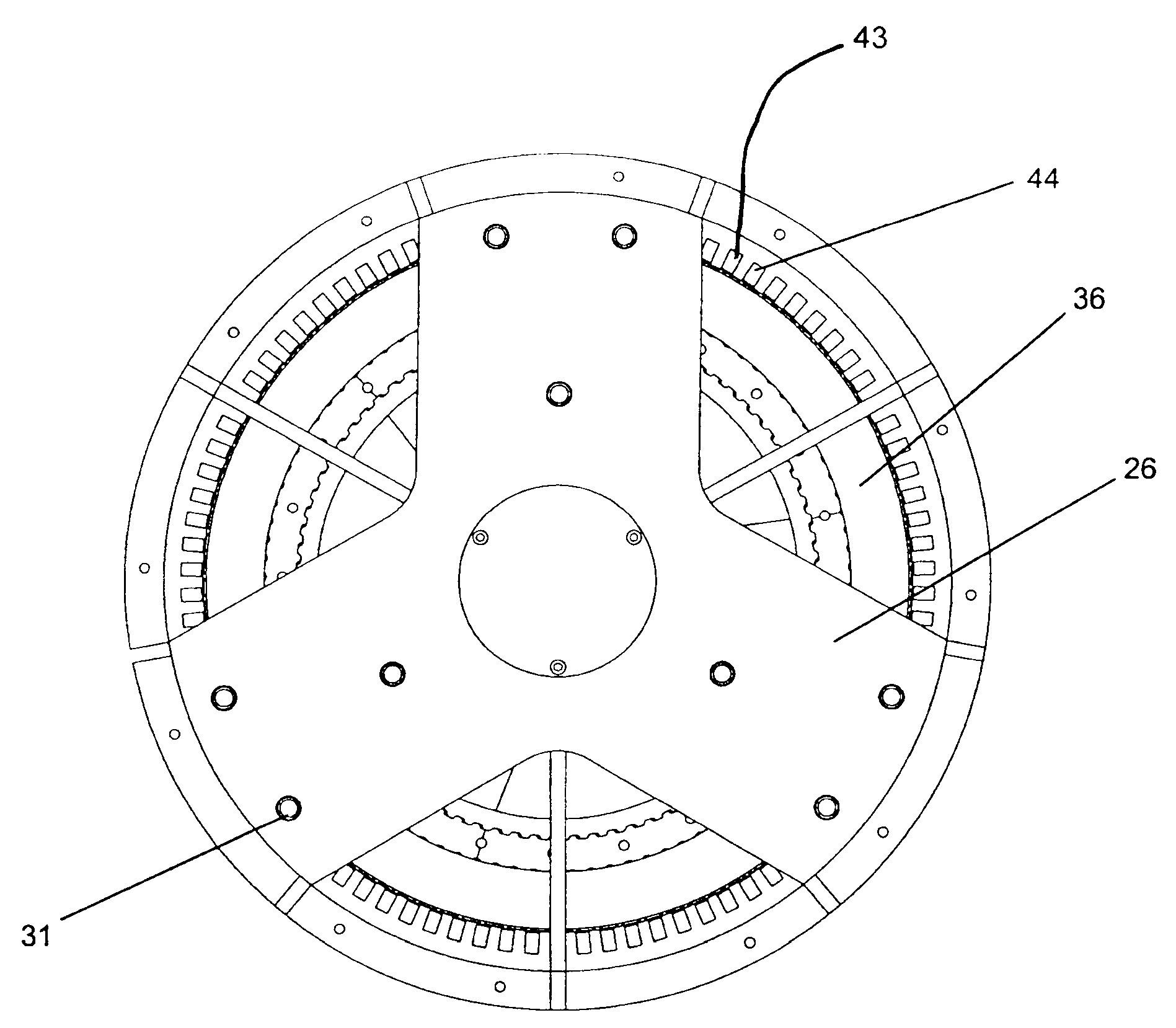
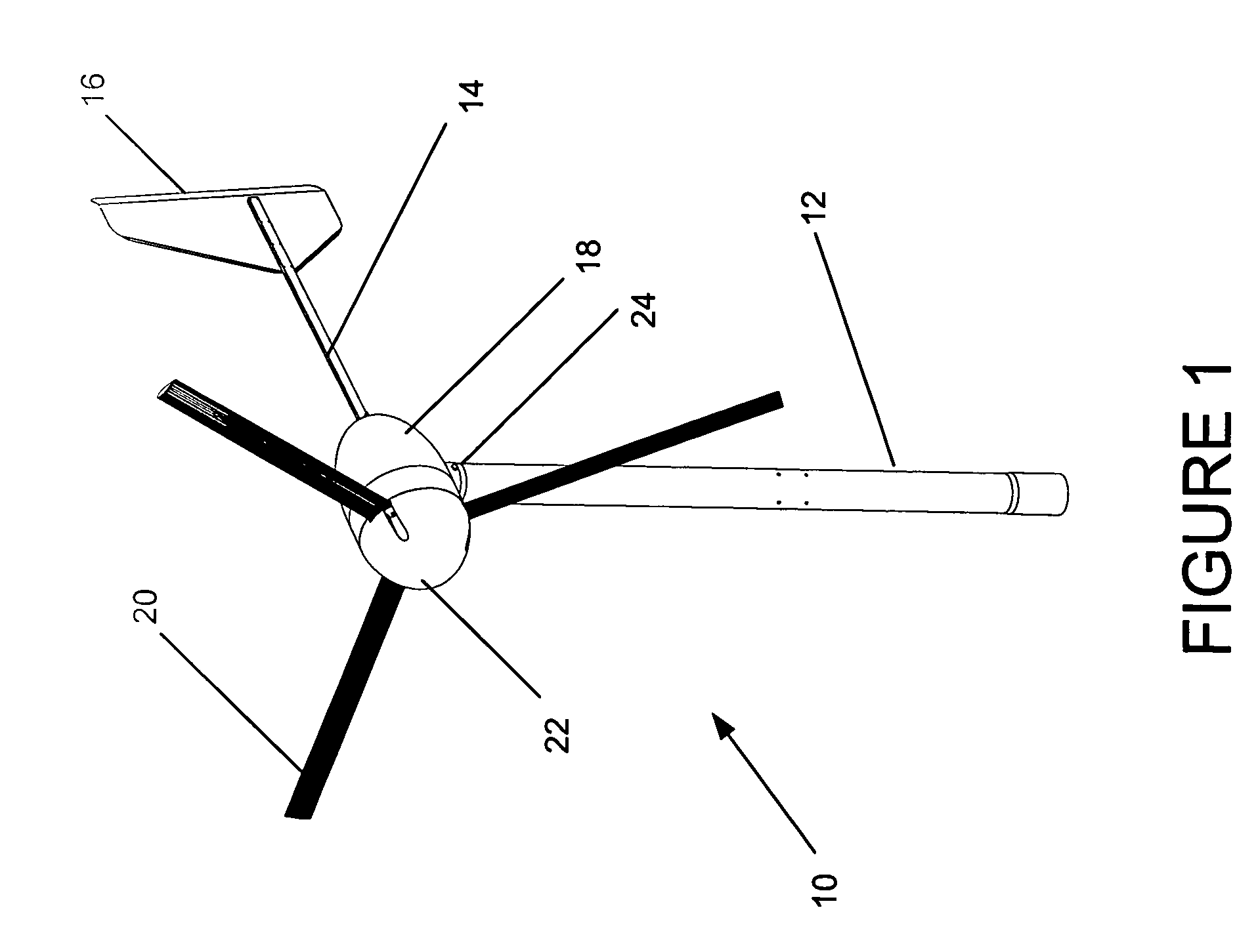
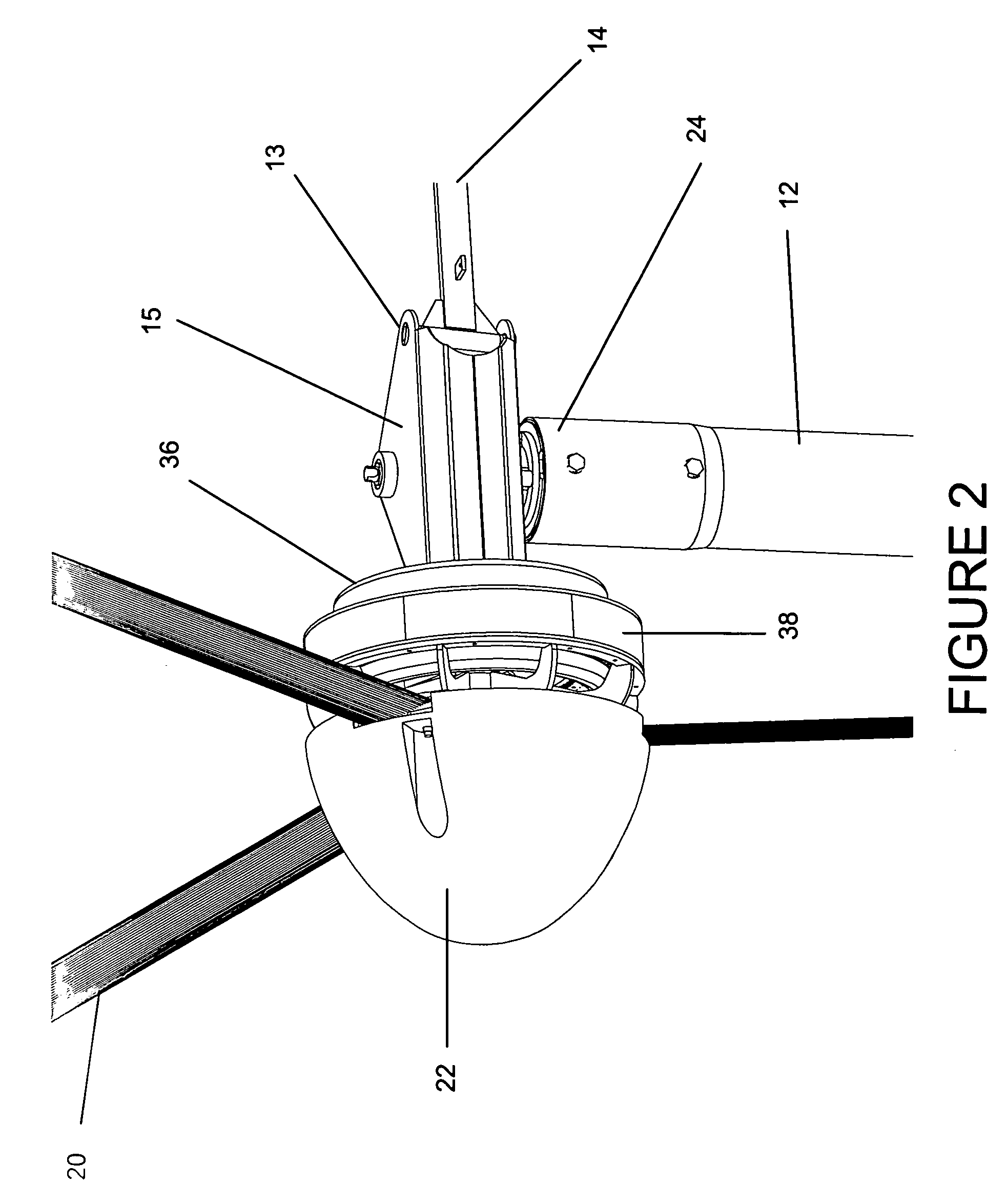
[0022]Referring first to FIGS. 1 and 2, which shows an isometric view of a wind turbine in accordance with the invention, a direct drive induction wind generator 10 may be pivotally disposed at the top distal end of tower 12 extending upwardly from the ground such that a plurality of airfoils or blades 20 may be acted upon by the wind. A fairing 18 may be provided to house the components of the generator 10 and also reduce aerodynamic forces and disturbances proximate to the airfoils 20. It should be noted, this particular embodiment depicts an upwind turbine design, which means a tail boom 14 is disposed on the wind generator 10 and a tail 16 is affixe...


PUM


Abstract

An electrical power generator is provided which is a direct drive induction generator capable of being directly connected to the power grid for the creation of electrical power. The rotor of the induction generator is located along the outside periphery of the stator and the stator may be provided with a plurality of poles. The number of poles provided on the stator may be adjusted to obtain an optimal rotational speed required to generate power. Using this arrangement, a low cost, efficient, reliable and easy to build wind generator may be provided.

Description

BACKGROUND OF THE INVENTION[0001]This invention relates to an electrical power generator and more specifically relates to a direct drive induction type generator which may be adaptable for use as a wind generator.[0002]Wind turbine generators are coming into more frequent use as an alternative electrical power source. Wind farms use induction generators to convert the rotary movement of a wind turbine to electrical power. The fact that the wind velocity is random, unpredictable and subject to rapid changes complicates the manner in which the generator is connected to the AC power mains.[0003]Induction machines are inherently capable of operating either as generators or motors, depending on the rotational velocity of the prime mover drive. For velocities greater than the machine's synchronous speed, the machine will operate in a generating mode and provide a power output to the mains. However, for velocities below the synchronous speed, the machine will operate in a motoring mode and...

Claims


Application Information

Patent Timeline
Patent Type & Authority Patents(United States)
IPC IPC(8): F03D9/00H02P9/00
CPCF03D1/00F03D9/002H02K7/183H02K17/42H02P9/48F05B2220/7066H02P2101/15Y02E10/725H02K17/14F03D9/25F03D9/255F03D15/20F03D80/70Y02E10/72
Inventor BLITTERSDORF, DAVID C.
Owner EARTH TURBINES
Learn More