ESD protection device

a protection device and electrostatic discharge technology, applied in the direction of electrostatic charges, overvoltage arrestors using spark gaps, electrical equipment, etc., can solve the problems of damage or malfunction of electronic devices, deterioration of the function of an esd protection device, and difficulty in precisely setting the starting voltage of the discharg

Active Publication Date: 2009-12-15
MURATA MFG CO LTD
View PDF6 Cites 33 Cited by
  • Summary
  • Abstract
  • Description
  • Claims
  • Application Information

AI Technical Summary

Benefits of technology

[0010]To overcome the problems described above, preferred embodiments of the present invention provide a reliable ESD protection device having a precise discharge starting voltage.

Problems solved by technology

ESD causes damage or malfunctioning of electronic devices.
An excessively high voltage generated by static electricity, for example, through an antenna of a mobile phone causes discharge between the discharge electrodes of the ESD protection device, which discharges the static electricity to the ground.
First, the discharge starting voltage depends primarily on the distance between discharge electrodes. However, the distance between the discharge electrodes may vary due to lot-to-lot variations or differences in shrinkage between a ceramic multilayer board and the discharge electrodes during a firing process. This produces variations in the discharge starting voltage of an ESD protection device. It is therefore difficult to precisely set the discharge starting voltage.
Second, the discharge electrodes disposed in a cavity may be detached from a ceramic multilayer board due to a reduced airtightness of the cavity or different thermal expansion coefficients between the substrate layers of the ceramic multilayer board and the discharge electrodes. This deteriorates the function of an ESD protection device, or alters the discharge starting voltage, which reduces the reliability of the ESD protection device.

Method used


Image

  • ESD protection device
  • ESD protection device
  • ESD protection device

Examples


first preferred embodiment

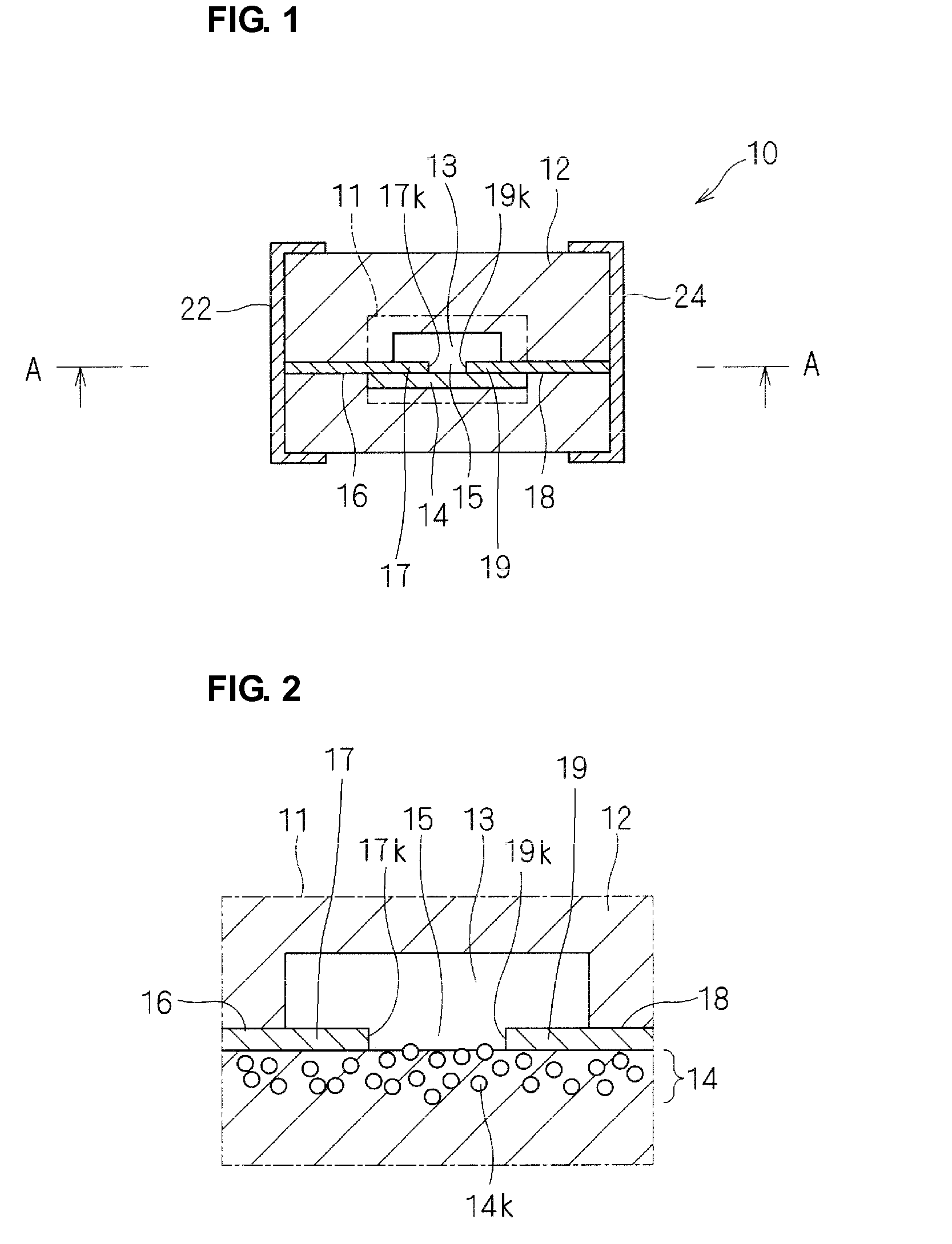
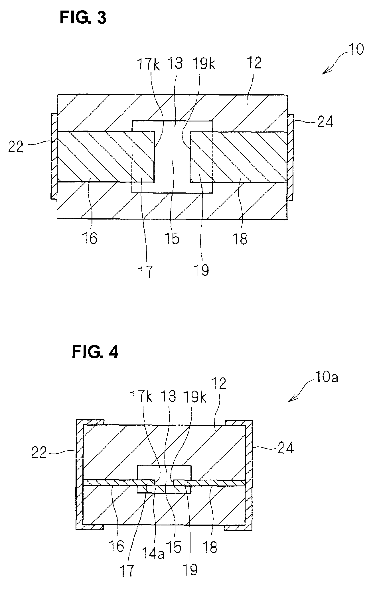
[0052]An ESD protection device 10 according to a first preferred embodiment will be described below with reference to FIGS. 1 to 3. FIG. 1 is a cross-sectional view of the ESD protection device 10. FIG. 2 is a schematic enlarged cross-sectional view of a principal portion of a region 11 indicated by a chain line in FIG. 1. FIG. 3 is a cross-sectional view taken along line A-A in FIG. 1.

[0053]As illustrated in FIG. 1, the ESD protection device 10 includes a ceramic multilayer board 12 having a cavity 13. Opposed ends 17 and 19 of discharge electrodes 16 and 18 are disposed in the cavity 13. The discharge electrodes 16 and 18 extend to side surfaces of the ceramic multilayer board 12 and are connected to external electrodes 22 and 24 disposed on an outer surface of the ceramic multilayer board 12. The external electrodes 22 and 24 are arranged to mount the ESD protection device 10.

[0054]As illustrated in FIG. 3, the ends 17 and 19 of the discharge electrodes 16 and 18 are opposed to e...

second preferred embodiment

[0086]An ESD protection device 10a according to a second preferred embodiment will be described below with reference to FIG. 4. The ESD protection device 10a according to the second preferred embodiment has a structure that is similar to that of the ESD protection device 10 according to the first preferred embodiment. Thus, points of difference will primarily be described below. Like reference numerals denote like components.

[0087]FIG. 4 is a cross-sectional view of the ESD protection device 10a substantially perpendicular to the discharge electrodes 16 and 18, as in FIG. 1. As illustrated in FIG. 4, a composite portion 14a is disposed directly under a cavity 13. In other words, the composite portion 14a is disposed on a side of the cavity 13 and has a width that is less than that of the cavity 13, when viewed from above the ESD protection device 10a (in the vertical direction).

[0088]The composite portion 14a disposed directly under the cavity 13 reduces variations in the shape of t...

third preferred embodiment

[0089]An ESD protection device 10b according to a third preferred embodiment will be described below with reference to FIG. 5. The ESD protection device 10b according to the third preferred embodiment has a structure that is similar to those of the ESD protection devices according to the first and second preferred embodiments. Thus, points of difference will primarily be described below. Like reference numerals denote like components.

[0090]FIG. 5 is a cross-sectional view of the ESD protection device 10b substantially perpendicular to the discharge electrodes 16b and 18b. As illustrated in FIG. 5, the ESD protection device 10b includes the discharge electrodes 16b and 18b disposed in a central portion of a ceramic multilayer board 12, internal electrodes 36 and 38 disposed on a plane that is different from a plane on which the discharge electrodes 16b and 18b are disposed, and via electrodes 32 and 34 disposed between the discharge electrodes 16b and 18b and the internal electrodes ...


PUM

PropertyMeasurementUnit
temperatureaaaaaaaaaa
thicknessaaaaaaaaaa
particle sizeaaaaaaaaaa

Abstract

An ESD protection device includes a ceramic multilayer board, a cavity disposed in the ceramic multilayer board, at least one pair of discharge electrodes having ends, edges of the ends being opposed to each other at a predetermined distance in the cavity, and external electrodes disposed on outer surfaces the ceramic multilayer board and connected to the discharge electrodes. The ceramic multilayer board includes a composite portion, which is disposed in the vicinity of the surface on which the discharge electrodes are disposed and is at least disposed adjacent to the opposed ends of the discharge electrodes and to a space between the opposed ends. The composite portion includes a metal material and a ceramic material.

Description

BACKGROUND OF THE INVENTION[0001]1. Field of the Invention[0002]The present invention relates to an electrostatic discharge (ESD) protection device and more particularly, to a technique for preventing a fracture caused by cracking and the deformation of a ceramic multilayer board in an ESD protection device that includes opposed discharge electrodes in a cavity of the ceramic multilayer board.[0003]2. Description of the Related Art[0004]ESD is a phenomenon in which a charged electroconductive body (for example, the human body) comes into contact with or comes into close proximity to another electroconductive body (for example, an electronic device) and discharges electricity. ESD causes damage or malfunctioning of electronic devices. To prevent ESD, it is necessary to protect circuits of the electronic devices from an excessively high discharge voltage. ESD protection devices, which are also known as surge absorbers, have been used.[0005]An ESD protection device may be disposed betw...

Claims


Application Information

Patent Timeline
Patent Type & Authority Patents(United States)
IPC IPC(8): H02H9/00
CPCH01T4/12H01T4/10
Inventor URAKAWA, JUN
Owner MURATA MFG CO LTD
Why Eureka
Try Eureka