Machine tool control console

a technology of control console and machine tool, which is applied in the direction of mechanical control devices, manual control with single controlling member, instruments, etc., can solve the problems of operator fatigue, operator hand fatigue, and operator hand fatigue,

Inactive Publication Date: 2009-12-22
CATERPILLAR INC
View PDF68 Cites 31 Cited by
  • Summary
  • Abstract
  • Description
  • Claims
  • Application Information

AI Technical Summary

Problems solved by technology

These optional work tools can be relatively complicated and difficult to operate.
After a period of operating these control mechanisms, the operators may become fatigued, with no way to rest the hand or arm while operating the various control mechanisms.
Further, because an operator's hand may be required to travel from one actuating element to another, an operator's delayed reaction time and the complexity and counter-intuitiveness of the controls may result in poor quality and / or low production.
Also, because these single-axis lever control mechanisms are not location-adjustable, they may be inefficiently and / or non-ergonomically-located for all machine operators.
Although the arrangement of the '141 patent may alleviate some of the problems associated with separate work machine controls, the arrangement may be ineffective for controlling work tools available to a work machine.
This requirement may unnecessarily increase the overall cost of the base work machine.
Further, the arrangement of the '141 patent may not provide enough support or adjustability to the machine operator.

Method used


Image

  • Machine tool control console
  • Machine tool control console
  • Machine tool control console

Examples


Embodiment Construction

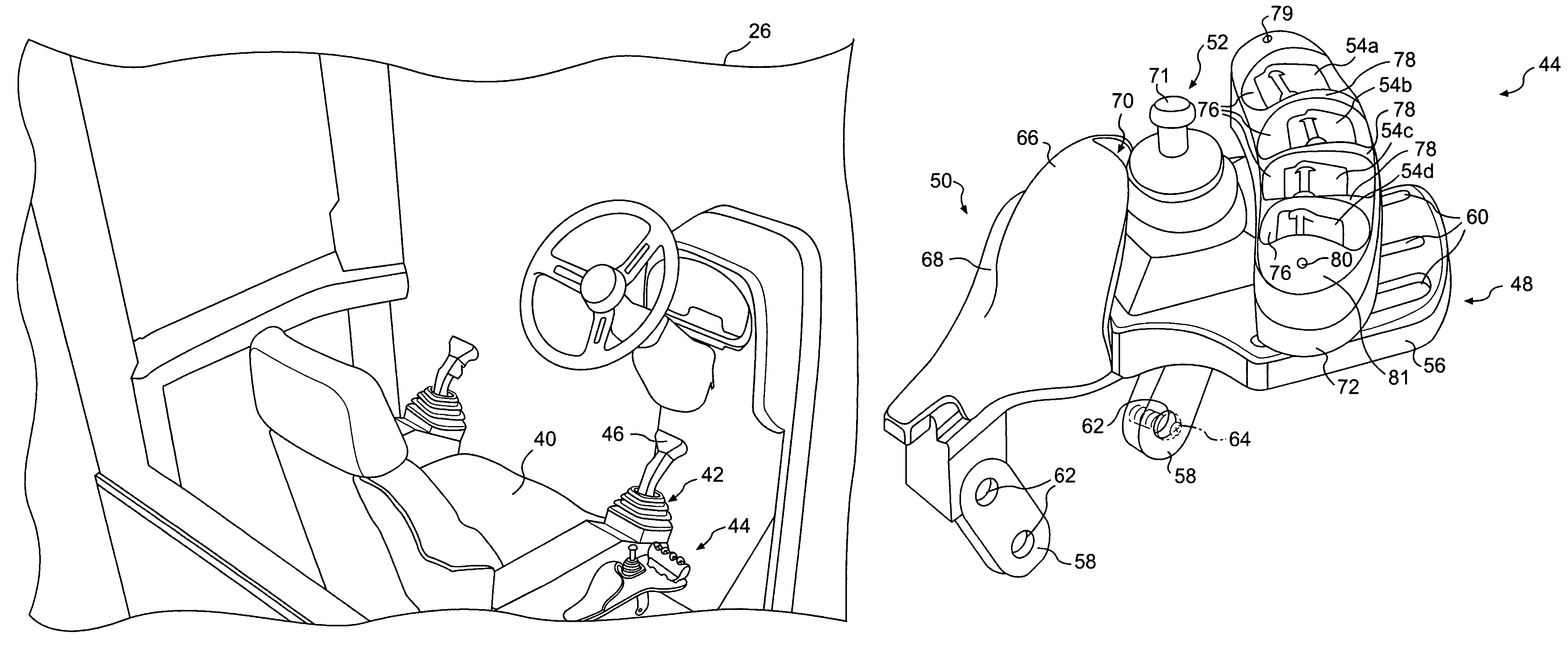
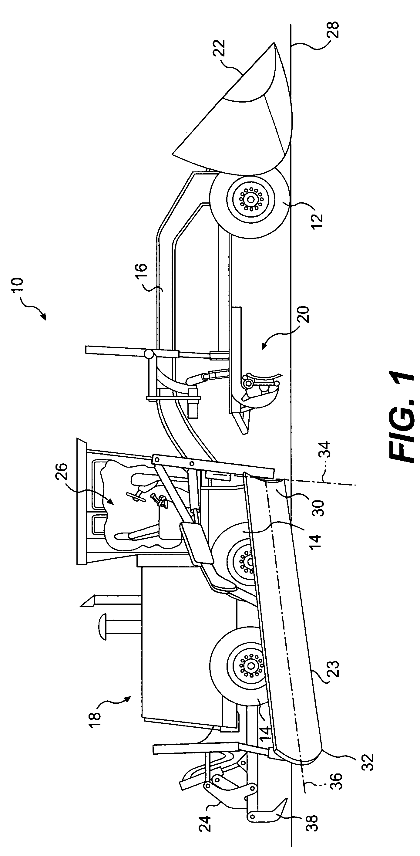
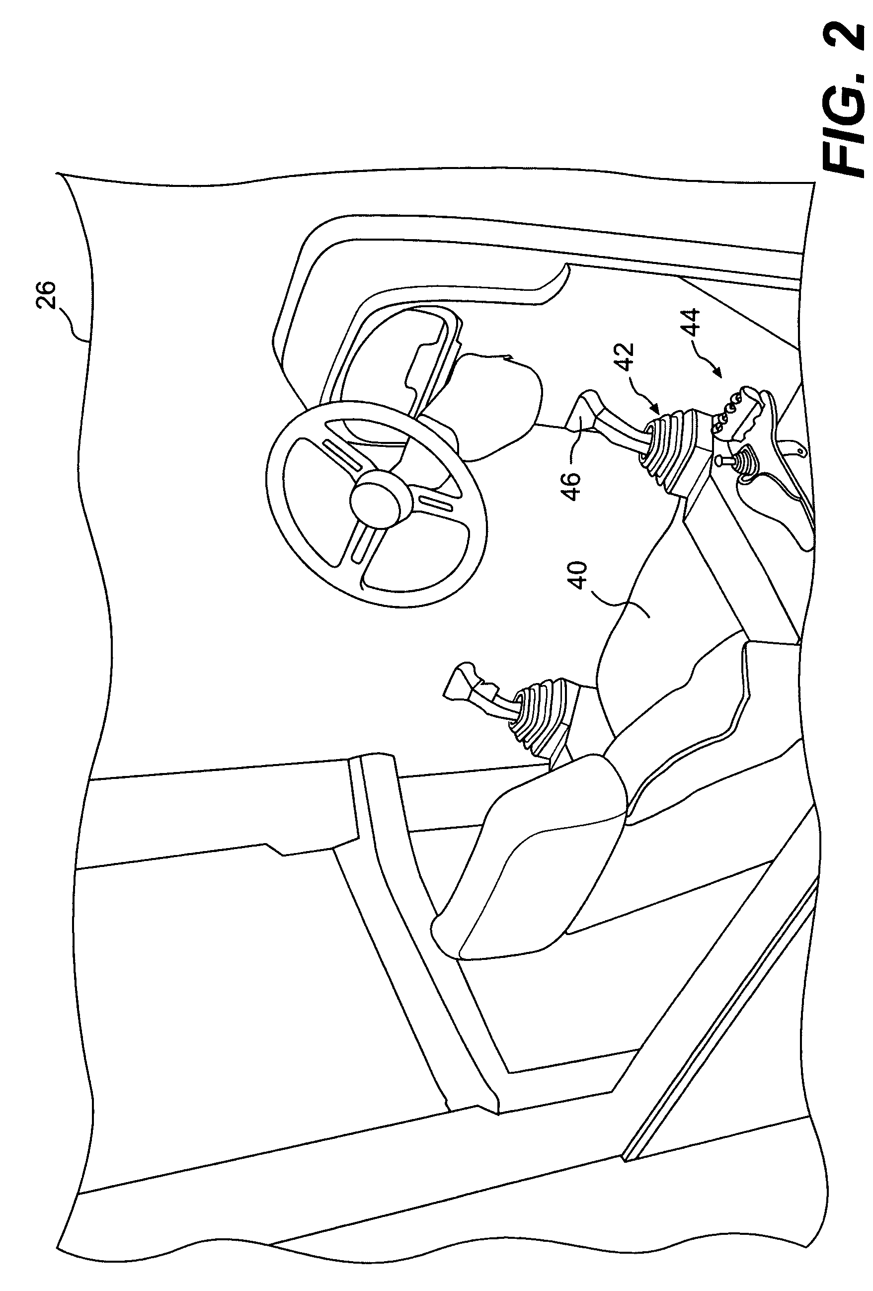
[0014]An exemplary embodiment of a work machine 10 is illustrated in FIG. 1. Work machine 10 may be a fixed or mobile machine that performs some type of operation associated with an industry such as mining, construction, farming, or any other industry known in the art. For example, work machine 10 may be an earth moving machine such as a dozer, a loader, an excavator, a motor grader, a dump truck, or any other earth moving machine. Work machine 10 may include a steerable traction device 12, a driven traction device 14, a frame 16 connecting steerable traction device 12 to driven traction device 14, and a power source 18 supported by driven traction device 14. Work machine 10 may also include a permanent work tool 20, a plurality of optional work tools 22-24, and an operator station 26.

[0015]Steerable traction device 12 may include one or more wheels located on each side of work machine 10 (only one side shown). Alternately, steerable traction device 12 may include tracks, belts, or ...


PUM


Abstract

A control console for a work machine having at least one work tool has a rest and a plurality of operator control devices. The plurality of operator control devices are adjustable relative to the rest and configured to control at least one function of the at least one work tool.

Description

TECHNICAL FIELD[0001]The present disclosure is directed to a work machine control console and, more particularly, to a control console that controls optional work machine tools.BACKGROUND[0002]Work machines such as, for example, motor graders, backhoe loaders, agricultural tractors, and other types of heavy machinery may have a variety of optional work tools that can be attached to and controlled by the work machine. These optional work tools can be relatively complicated and difficult to operate. Each work tool may have a different operator interface with numerous controls for position, orientation, and other associated features and functions.[0003]Historically, work machines have incorporated permanently located single-axis lever control mechanisms with complex mechanical linkages and multiple operating joints, or a plurality of cables to provide the desired work tool functionality. Such control mechanisms require operators with high skill levels to control the many input devices....

Claims


Application Information

Patent Timeline
Patent Type & Authority Patents(United States)
IPC IPC(8): B60K26/00B62D1/22
CPCE02F9/2004G05G9/047
Inventor SHEARER, DANIEL EDWARDKELLEY, CRAIG B.LEADERS, ROYCE E.
Owner CATERPILLAR INC
Why Eureka
Try Eureka