Surveying instrument and method of controlling a surveying instrument

a surveying instrument and instrument control technology, applied in the direction of programme control, optical radiation measurement, distance measurement, etc., to achieve the effect of better suitable tracking targets

Active Publication Date: 2009-12-29
TRIMBLE INC
View PDF12 Cites 26 Cited by
  • Summary
  • Abstract
  • Description
  • Claims
  • Application Information

AI Technical Summary

Benefits of technology

[0009]Embodiments of the present invention provide surveying instruments and control methods which are improved with respect to maintaining tracking of a desired target even when another target is located within a field of view of a tracking detector.
[0011]This method includes using two types of light having intensities which are modulated according to different time patterns. The modulation of the light according to known time patterns allows the measuring instrument to distinguish light modulated according to the first time pattern from light modulated according to the second time pattern and also from other light received by the surveying instrument through the same lens and detected by the same detector. The received light may include stray light and light originating from other objects within a field of view of the detector of the surveying instrument.
[0015]According to an embodiment of the present invention, the surveying instrument and control method use the light modulated according to a first time pattern for controlling an orientation of the measuring unit relative to the base in a first angular direction, and use the light modulated according to a second time pattern for controlling the orientation of the measuring unit relative to the base in a second angular direction which is different from the first angular direction. Such usage of the different types of light for controlling the orientation of the measuring unit in different angular directions may allow for a robust tracking of a desired target.
[0019]According to an exemplary embodiment, the controlling of the actuators is performed such that at least one of the first and second spots covers portions of at least two detector segments. For example, the controlling may be performed such that light intensities detected by the at least two detector segments are about equal. In such situation, a center of the spot will be located close to a insulated barrier between the at least two detector segments. Such configuration allows detection of displacements of the spot on the detector with a relatively high accuracy.

Problems solved by technology

A problem might arise if a second target, which should not be tracked, appears within the field of view of the detector, where it might happen that the instrument then continues tracking with respect to the second target rather than the first target which should be tracked.

Method used


Image

  • Surveying instrument and method of controlling a surveying instrument
  • Surveying instrument and method of controlling a surveying instrument
  • Surveying instrument and method of controlling a surveying instrument

Examples


Embodiment Construction

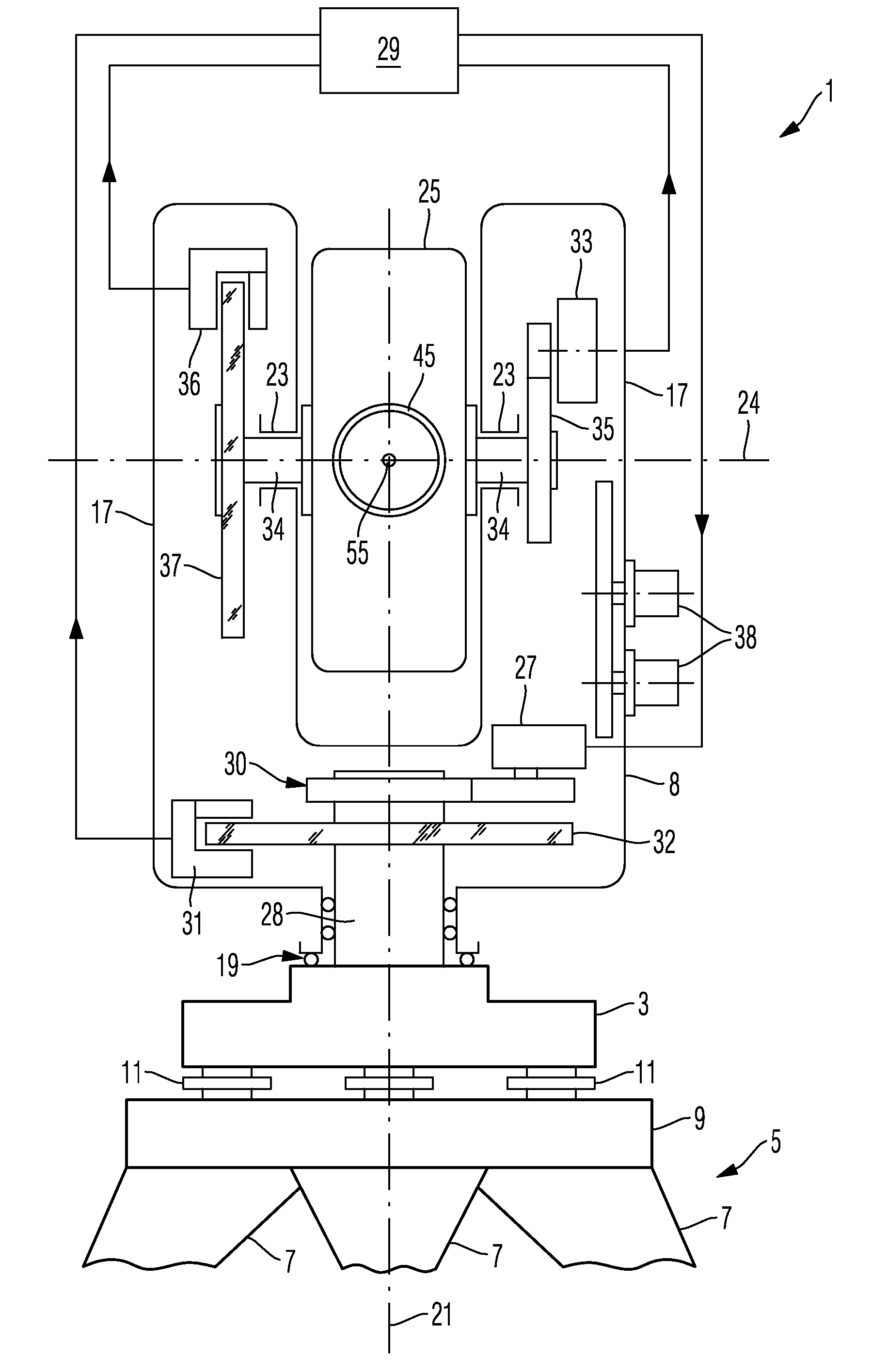
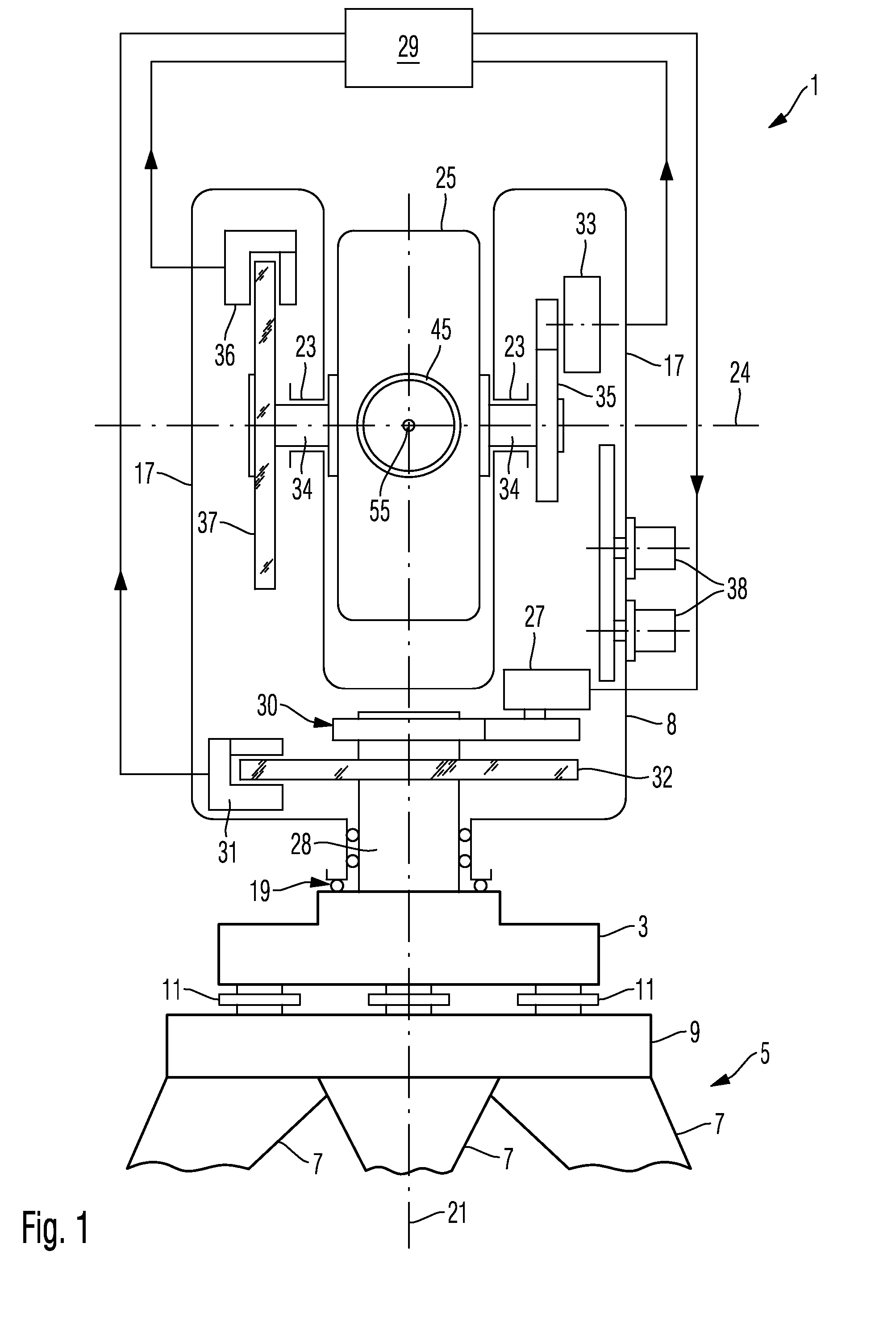
[0042]FIG. 1 is an illustration of a surveying instrument which may be used according to embodiments of the invention. The surveying instrument 1 is a electro-optical distance measuring instrument which is also referred to as a total station in the art. The instrument is mounted on a base 3 of a tripod 5. The tripod 5 comprises three legs 7 attached to a plate 9. The base 3 is mounted on the plate 9 by three screws 11 allowing leveling of the base 3 relative to a ground on which the legs are placed.

[0043]The base 3 carries a swivel arrangement comprising a pair of brackets 17 mounted on the base 3 by a bearing arrangement 19 such that the pair of brackets 17 is rotatable relative to the base 3 about a vertical axis 21. A bearing 23 is provided in each of the brackets 17 to define a common horizontal axis 24 about which an optical measuring unit 25 is rotatable.

[0044]An actuator arrangement, such as a motor arrangement 27 carried by the brackets 17 engages with a pin 28 fixed to the ...


PUM


Abstract

A surveying instrument performs tracking of a target by controlling an orientation of a measuring unit relative to the target in two different angular directions. The control in one angular direction is based on detected light intensities which are modulated according to a first time pattern, and control of the orientation in the other angular direction is based on detected light intensities modulated according to a second time pattern just different from the first time pattern.

Description

CROSS-REFERENCE TO RELATED APPLICATIONS[0001]This application claims the benefit of European Patent Application No. 06 013 742.9 filed Jul. 3, 2006.BACKGROUND OF THE INVENTION[0002]1. Field of the Invention[0003]The present invention generally relates to surveying instruments and methods of controlling surveying instruments. The invention also relates to a computer-readable carrier embodying a program for controlling surveying instruments. In particular, the present invention relates to surveying instruments which are configured to measure angles and / or distances relative to a target.[0004]2. Brief Description of Related Art[0005]It is known to use surveying instruments for measuring distances between objects and angles in a coordinate system, wherein the surveying instrument is placed at a predetermined position relative to one object and wherein a suitable target is placed at a predetermined position relative to the other object, and wherein the surveying instrument performs an el...

Claims


Application Information

Patent Timeline
Patent Type & Authority Patents(United States)
IPC IPC(8): G05B19/18G01B11/26G01C3/08G01C1/00
CPCG01C15/002G01S17/42G01S7/4811G01S3/784
Inventor JOHNSON, JOHANUTTERBACK, ANNELI
Owner TRIMBLE INC
Why Eureka
Try Eureka