Magnetostriction type torque sensor

a torque sensor and magnetostriction technology, applied in the field of magnetostriction type torque sensors, can solve the problems of difficult to distinguish the normal state from the on-failure state, and achieve the effect of preventing excessive current and disconnection

Active Publication Date: 2010-01-05
HONDA MOTOR CO LTD
View PDF10 Cites 3 Cited by
  • Summary
  • Abstract
  • Description
  • Claims
  • Application Information

AI Technical Summary

Benefits of technology

[0007]In view of the above, an object of the present invention is to provide a magnetostriction type torque sensor which distinguishes a normal state from a failure state of a switching element.
[0009]In the magnetostriction type torque sensor, the magnetic property of the magnetic property change material changes in accordance with the torque applied to the shaft. Moreover, the excitation signal generator applies the excitation signal to the plurality of the detection coils. Accordingly, the change of the magnetic property is detected based on the voltage between the connection points between the detection coils. At this time, the operational state monitor monitors the operational states of the switching elements so as to prevent excessive current and disconnection due to an ON-failure in the switching element.

Problems solved by technology

Therefore, it is difficult to distinguish the normal state from the ON-failure state.

Method used


Image

  • Magnetostriction type torque sensor
  • Magnetostriction type torque sensor
  • Magnetostriction type torque sensor

Examples


first embodiment

[0030]A magnetostriction type torque sensor unit according to an embodiment of the present invention will be described, below.

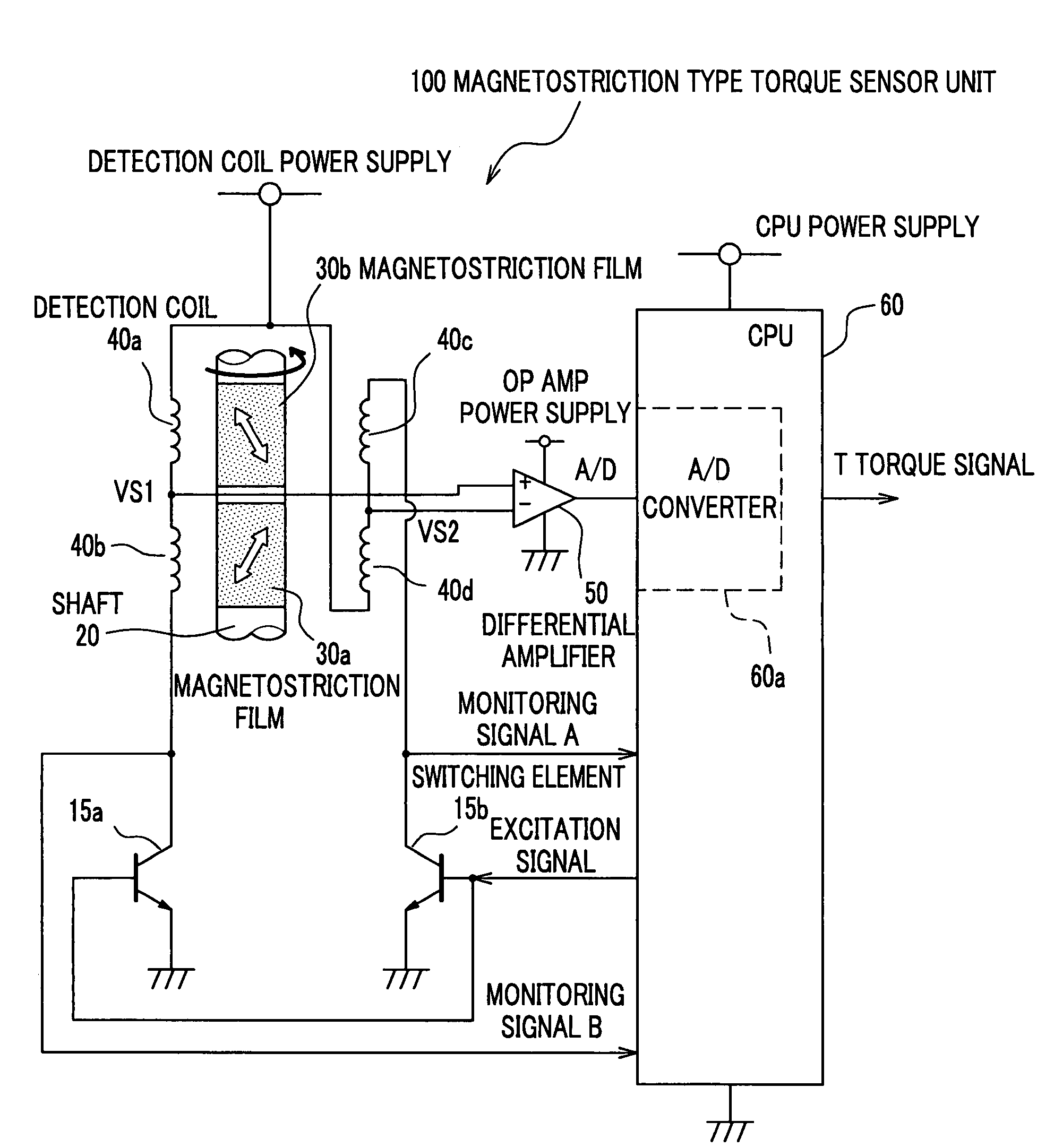
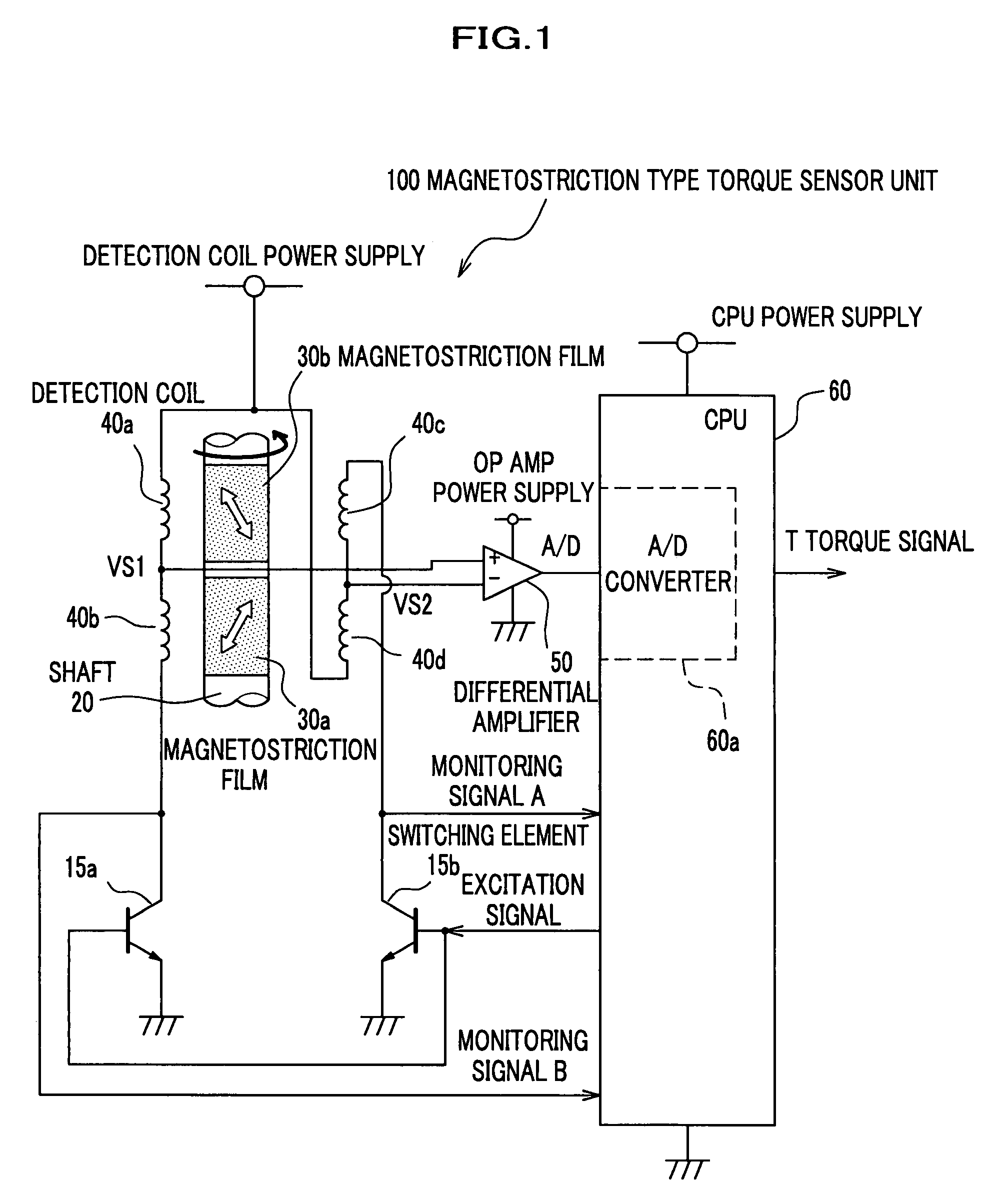
[0031]A magnetostriction type torque sensor unit 100 shown in FIG. 1 is used to detect torque applied to a steering shaft in an electric power steering device which will be described later. The magnetostriction type torque sensor unit 100 includes magnetostriction films (magnetic property change material, or a first magnetostriction film and a second magnetostriction film) 30a and 30b which are attached in the axial direction on the two parts of the shaft (steering shaft) 20 which are close to each other, detection coils 40a and 40b which are connected in a series and detection coils 40c and 40d which are connected in a series in an opposite direction to the detection coils 40a and 40b, a differential amplifier 50 which calculates a differential voltage between a connection point VS1 between the detection coils 40a and 40b, and a connection point VS2 between ...

second embodiment

[0043]In the first embodiment, the switching elements 15a and 15b are used to apply the positive rectangular waveform voltage to the detection coils 40a and 40b or the detection coils 40c and 40d. On the other hand, a bridge circuit can be used to apply a rectangular waveform AC voltage.

[0044]Next, referring to FIG. 3, a magnetostriction type torque sensor unit 150 according to a second embodiment of the present invention will be described. Here, the shaft 20, the magnetostriction films 30a and 30b, the differential amplifier 50, and the CPU 60 are similar to those in the first embodiment. Therefore, only different features from the first embodiment will be described, below.

[0045]A bridge circuit 10 includes four switching elements 10a, 10b, 10c, and 10d. The switching elements 10a and 10c are p channel MOSFETs while the switching elements 10b and 10d are n channel MOSFETs. The drains of the switching elements 10a and 10c are connected to a detection coil power supply, while the sou...

example use

[0054]Next, referring to FIG. 6, description will be given to an electric power steering device which employs the magnetostriction type torque sensor unit 100 or 150 according to the embodiments.

[0055]In an electric power steering device 200, a steering wheel 210 is rotated. Then, the shaft 20, which is a steering shaft directly connected to the steering wheel 210, rotates a pinion 260 included in a rack-and-pinion 270. Accordingly, a rack shaft 250 is moved so as to change a direction of the rolling wheel 220. Then, a controller 230 controls to drive an electric motor 240 in accordance with a torque signal T which is detected by the magnetostriction type torque sensor unit 100 or 150 using detection coils 40. The electric motor 240 rotates the pinion 260 through a force transmitter 280 and operates to reduce steering torque of the steering wheel 210. There is the following relationship.

TH=TP / (1+KA),

where steering torque of a driver is TH, torque transferred to the pinion 260 is TP,...


PUM

PropertyMeasurementUnit
voltagesaaaaaaaaaa
magnetostrictionaaaaaaaaaa
magnetic propertyaaaaaaaaaa

Abstract

A magnetostriction type torque sensor is provided which includes magnetic property change material which is provided on a shaft and whose magnetic property changes in accordance with torque applied to the shaft, an excitation signal generator which generates an excitation signal whose voltage is converted into a predetermined voltage through a switching element, a plurality of detection coils to which the excitation signal generator applies the excitation signal, and which plurality of detection coils outputs voltage, which changes in accordance with change in the magnetic property of the magnetic property change material, between connection points between the detection coils, and an operational state monitor which monitors an operational state of the switching element.

Description

CROSS REFERENCE TO RELATED APPLICATIONS[0001]This application claims the foreign priority benefit under Title 35, United States Code, §119(a)-(d) of Japanese Patent Application No. 2006-113252, filed on Apr. 17, 2006 in the Japan Patent Office, the disclosure of which is herein incorporated by reference in its entirety.BACKGROUND OF THE INVENTION[0002]1. Field of the Invention[0003]The present invention relates to a magnetostriction type torque sensor which detects magnetic property change of magnetic property change material which is attached around a shaft.[0004]2. Description of the Related Art[0005]In an electric power steering device installed in a vehicle, a torque sensor detects torque which is given to a steering shaft by driver's steering. Thus, steering assist power is provided depending on torque signals output from the torque sensor. A magnetostriction type torque sensor is disclosed as such a torque sensor (See JP2004-239652A and JP2005-331453A). In this technology, a m...

Claims


Application Information

Patent Timeline
Patent Type & Authority Patents(United States)
IPC IPC(8): G01L3/00
CPCG01L3/102G01L3/105
Inventor YONEDA, ATSUHIKOSHIMIZU, YASUOSUEYOSHI, SHUNICHIROONIWA, YOSHIHIROARIMURA, YUTAKAMIYOSHI, TAKASHI
Owner HONDA MOTOR CO LTD
Why Eureka
Try Eureka