In-wheel motor with high durability

a high-durability, in-wheel motor technology, applied in the direction of propulsion parts, electric propulsion mounting, transportation and packaging, etc., can solve the problem of impaired durability of in-wheel motors, and achieve the effect of high durability

Inactive Publication Date: 2010-01-05
TOYOTA JIDOSHA KK +1
View PDF27 Cites 74 Cited by
  • Summary
  • Abstract
  • Description
  • Claims
  • Application Information

AI Technical Summary

Benefits of technology

[0013]An object of the present invention is to provide an in-wheel motor with high durability.
[0018]According to the present invention, durability of the in-wheel motor can be improved.

Problems solved by technology

Accordingly, there has been a problem with the conventional in-wheel motor drive scheme that the durability of the in-wheel motor is impaired.

Method used


Image

  • In-wheel motor with high durability
  • In-wheel motor with high durability
  • In-wheel motor with high durability

Examples


case 60

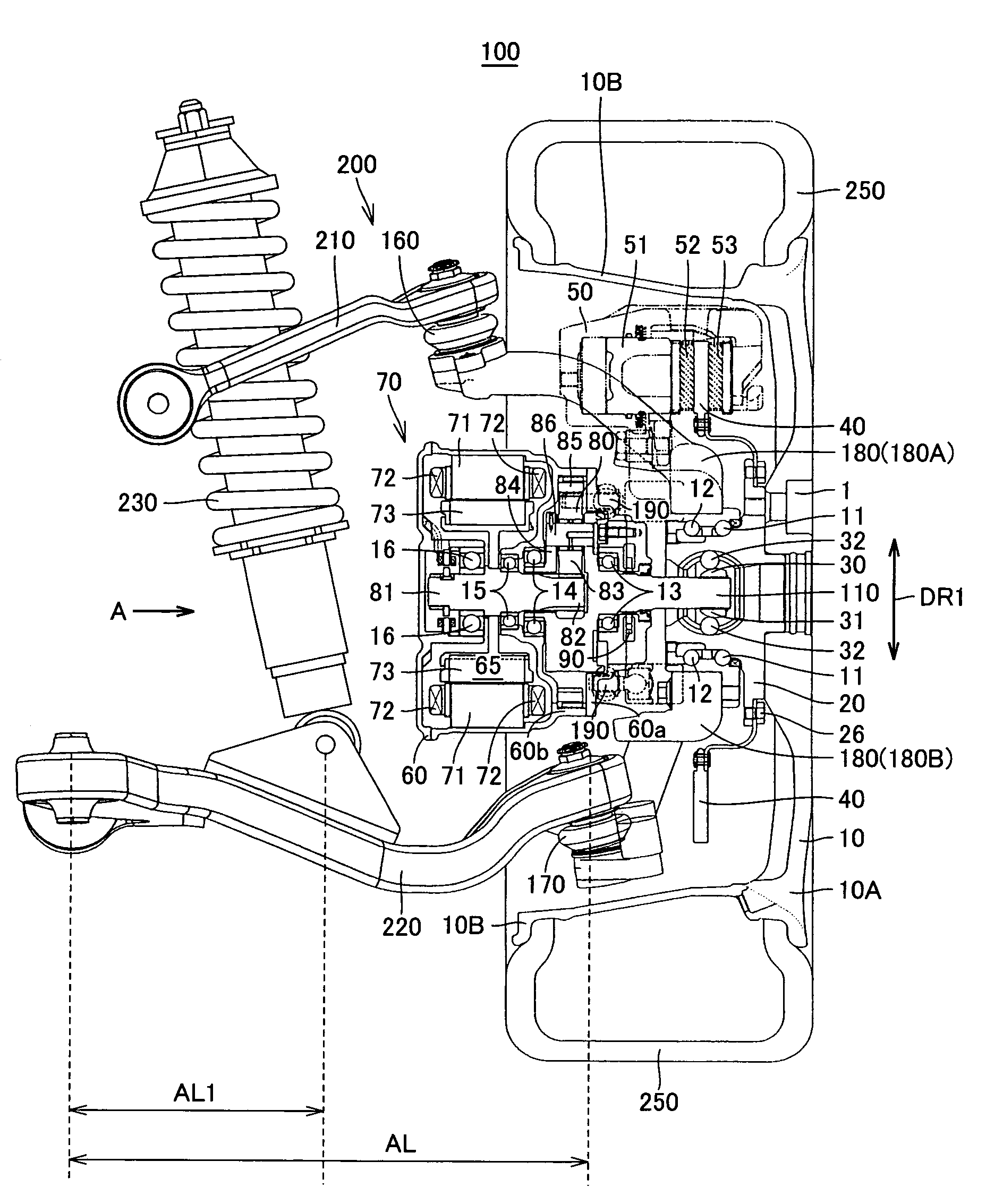
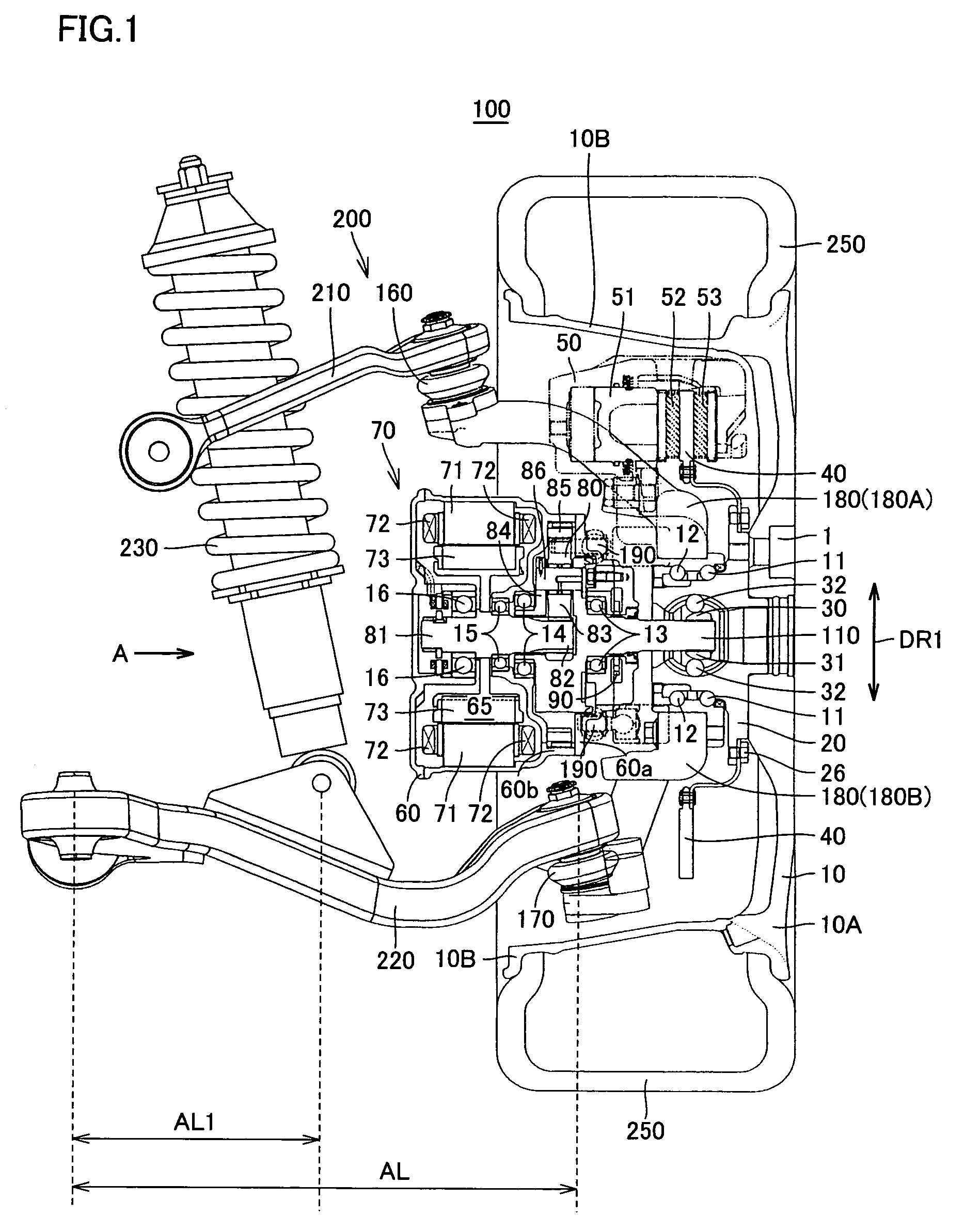
[0032]Case 60 is arranged on the left of wheel hub 20 in FIG. 1. Case 60 includes a case 60a and a case 60b. Case 60a has a substantially L shape, and case 60c has a substantially inverted C shape. Case 60a is arranged toward wheel disc 10, while case 60b is arranged toward the vehicle body. Case 60a and case 60b are coupled to each other by a not-shown screw, at faces perpendicular to the direction of the rotation shaft of shaft 110. Case 60a accommodates oil pump 90, shaft 110, and the oil passage. Case 60b accommodates motor 65 and planetary gear 80.

[0033]Motor 65 includes a stator core 71, a stator coil 72 and a rotor 73. Stator core 71 is fixed to case 60b. Stator coil 72 is wrapped around stator core 71. When motor 65 is a three-phase motor, stator coil 72 is formed by a U-phase coil, a V-phase coil, and a W-phase coil. Rotor 73 is arranged toward the inner circumference of stator core 71 and stator coil 72.

[0034]Planetary gear 80 includes a sun gear shaft 81, a sun gear 82, a...


PUM


Abstract

An in-wheel motor includes a motor generating motive power, a planetary gear arranged toward a wheel disc relative to the motor to reduce an output of the motor, and a shaft arranged toward the wheel disc relative to the planetary gear and connected to a planetary carrier. Shaft is connected to a constant velocity joint transmitting the motive power to wheel disc.

Description

[0001]This nonprovisional application is based on Japanese Patent Application No. 2005-001801 filed with the Japan Patent Office on Jan. 6, 2005, the entire contents of which are hereby incorporated by reference.BACKGROUND OF THE INVENTION[0002]1. Field of the Invention[0003]The present invention relates to an in-wheel motor, and particularly, to an in-wheel motor with high durability.[0004]2. Description of the Background Art[0005]A known conventional in-wheel motor drive scheme is to support a hollow motor by a motor suspension (for example, see WO02 / 083446 and Go Nagaya, Yasumichi Wakao and Akihiko Abe “Development of an In-Wheel Motor with Advanced Dynamic-Damper Mechanism”, the society of automotive engineers of Japan, Nov. 26, 2002, proceedings of conference No. 83-02, pp. 9-12). The hollow motor is coupled to a wheel of a wheel unit to rotate the wheel. The hollow motor is supported by the motor suspension so that it can vibrate in the vertical direction of the vehicle, and t...

Claims


Application Information

Patent Timeline
Patent Type & Authority Patents(United States)
IPC IPC(8): B60K1/00B60K7/00F16H57/02
CPCB60K7/0007B60K17/046B60K2007/0092B60K2007/0053
Inventor MIZUTANI, RYOJIKURATA, FUMITOYOGO, SHIGEKAZUHARADA, KENJITORII, ATSUSHITOJIMA, YUKISAKUMA, MASAFUMI
Owner TOYOTA JIDOSHA KK
Why Eureka
Try Eureka