Dynamoelectric machine

a dynamoelectric machine and permanent magnet technology, applied in the direction of magnetic circuit rotating parts, magnetic circuit shape/form/construction, windings, etc., can solve the problems of permanent magnet wobble, increase in alternator size, increase in weight and installation space, etc., to suppress the occurrence of noise and increase the mass produced

Inactive Publication Date: 2010-01-05
MITSUBISHI ELECTRIC CORP
View PDF10 Cites 24 Cited by
  • Summary
  • Abstract
  • Description
  • Claims
  • Application Information

AI Technical Summary

Benefits of technology

[0010]The present invention aims to solve the above problems and an object of the present invention is to provide a dynamoelectric machine that enables mass producibility to be increased and also enables occurrences of noise that result from wobbling of a permanent magnet to be suppressed by enabling fixing of a permanent magnet by a resin material to be performed easily.
[0012]According to the present invention, because the resin injection aperture is formed so as to communicate between the external portion of the magnet holder and the adhesive space that is bounded by the permanent magnet, the magnet cover, and the receiving groove, the resin material can be injected through the resin injection aperture so as to fill the adhesive space after the permanent magnet and the magnet cover have been installed in the magnet holder. Thus, it is not necessary to apply the resin material to the permanent magnet and the magnet cover before the process of installing the permanent magnet and the magnet cover in the magnet holder, facilitating handling of the permanent magnet and the magnet cover, and enabling mass producibility to be increased. Because the adhesive space can be filled amply with the resin material through the resin injection aperture, the adhesive force of the permanent magnet and the magnet cover on the magnet holder is increased, suppressing the occurrence of noise that results from wobbling of the permanent magnet.

Problems solved by technology

If attempts are made to answer these demands within the scope of conventional design, the alternators are invariably increased in size.
Increases in alternator size increase weight and installation space.
Thus, one problem has been that the fastening force on the permanent magnets from the strap becomes loose, allowing the permanent magnets to wobble due to vibrations from the engine, etc., and generate noise.
However, the adhesive cannot be injected between the strap and the permanent magnets and between the permanent magnets and the mounting surfaces when the permanent magnets are held on the mounting surfaces by the strap.
Thus, the adhesive would have to be applied to the permanent magnets and the strap before the permanent magnets are held on the mounting surfaces, making handling of the magnetized permanent magnets and the strap problematic and reducing mass producibility.

Method used


Image

  • Dynamoelectric machine
  • Dynamoelectric machine
  • Dynamoelectric machine

Examples


embodiment 1

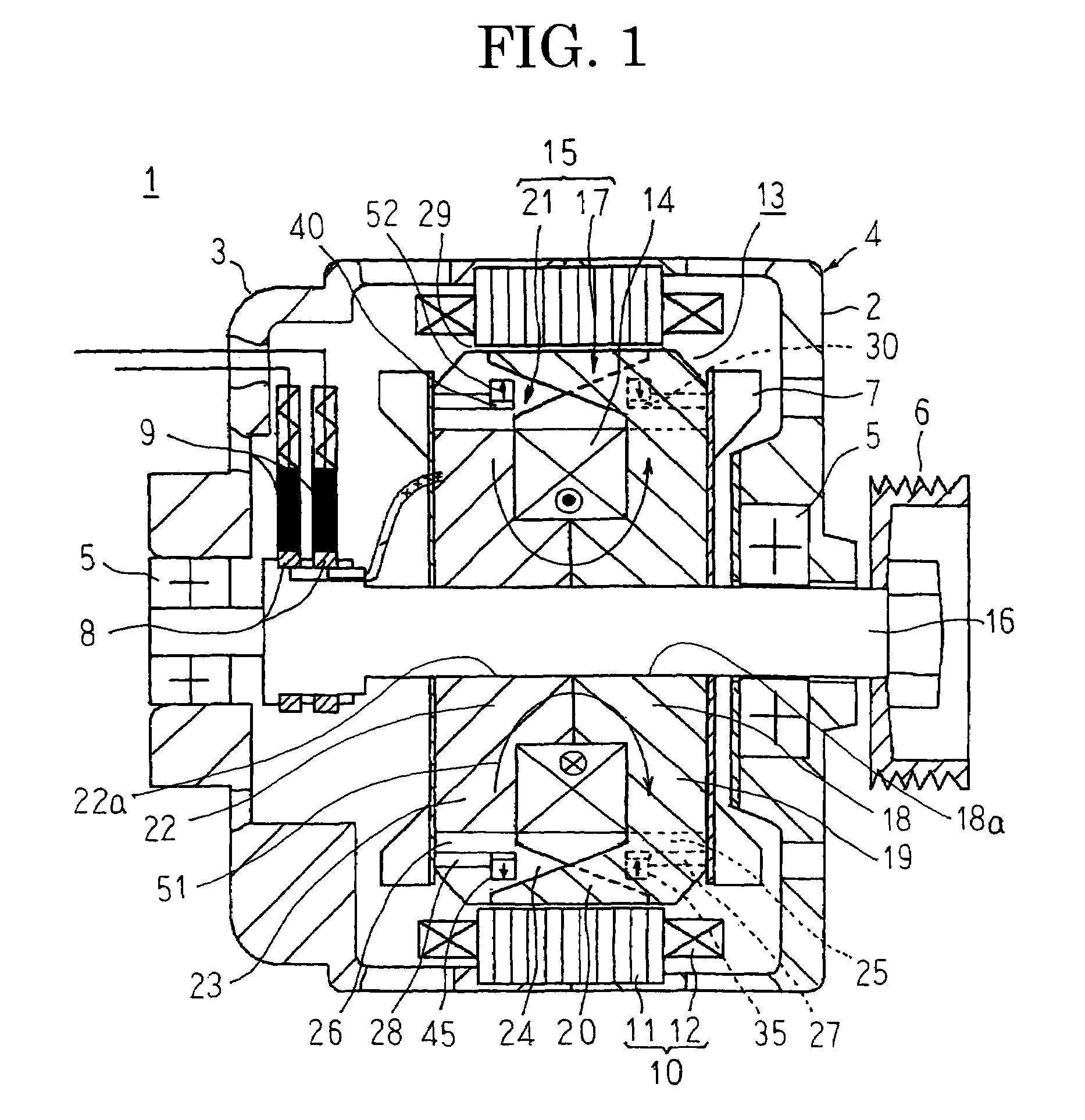
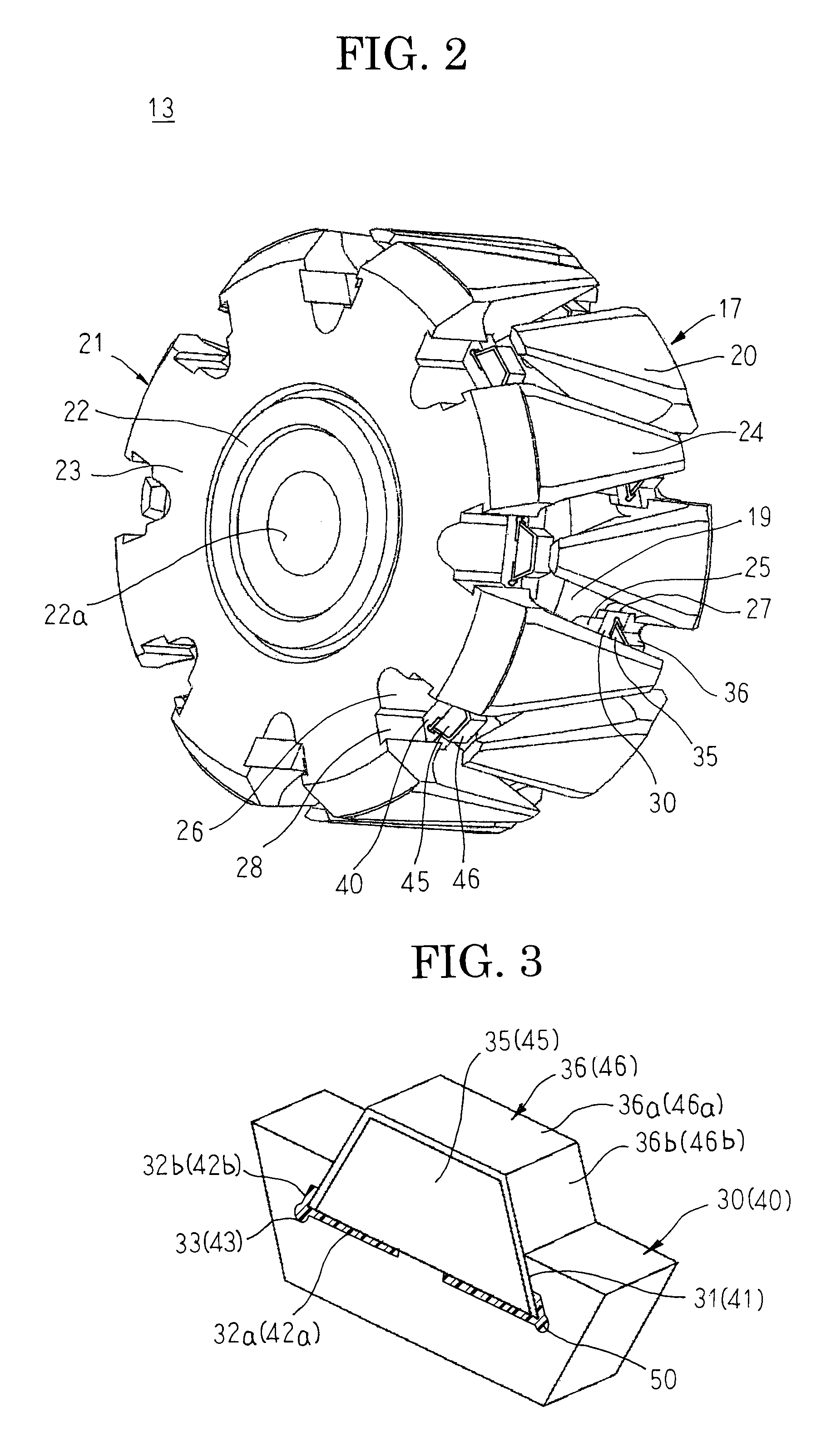
[0029]FIG. 1 is a cross section that schematically shows an automotive alternator according to Embodiment 1 of the present invention, FIG. 2 is a perspective of a rotor that can be used in the automotive alternator according to Embodiment 1 of the present invention, FIG. 3 is a perspective that shows a state in which a permanent magnet is mounted to a magnet holder in the automotive alternator according to Embodiment 1 of the present invention, FIG. 4 is a cross section that shows the state in which the permanent magnet is mounted to the magnet holder in the automotive alternator according to Embodiment 1 of the present invention, and FIG. 5 is a perspective of the magnet holder that can be used in the automotive alternator according to Embodiment 1 of the present invention.

[0030]In FIGS. 1 through 5, an automotive alternator 1 includes: a case 4 that is constituted by a front bracket 2 and a rear bracket 3 that are each made of aluminum so as to have an approximate cup shape; a rot...

embodiment 2

[0064]As shown in FIG. 6, Embodiment 2 is configured in a similar manner to Embodiment 1 above except for the fact that a first magnet cover 36A is used in which a pair of protective sides 36c are disposed so as to extend from two remaining opposite sides of the base portion 36a. Moreover, because a second magnet cover is also configured in a similar manner to the first magnet cover, only a first permanent magnet fixing construction will be explained here.

[0065]In Embodiment 2, a first magnet cover 36A is constituted by: a base portion 36a; a pair of wing portions 36b that are disposed so as to extend from two sides of the base portion 36a that face each other; and a pair of protective sides 36c that are disposed so as to extend from two remaining opposite sides of the base portion 36a. The first magnet cover 36A is mounted onto the first permanent magnet 35 by placing the base portion 36a on the upper surface of the first permanent magnet 35, bending the pair of wing portions 36b s...

embodiment 3

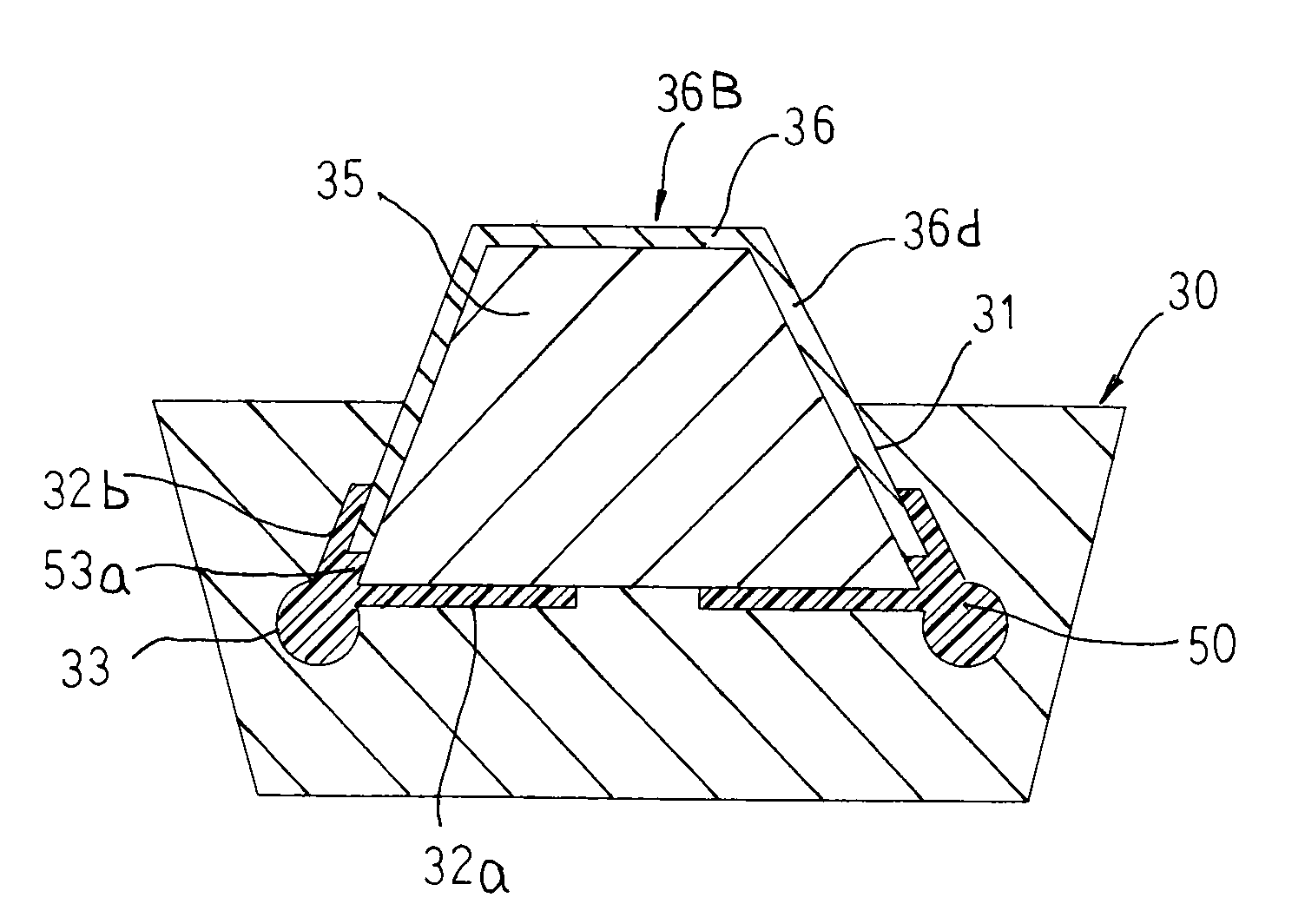
[0068]As shown in FIG. 7, Embodiment 3 is configured in a similar manner to Embodiment 1 above except for the fact that a first magnet cover 36B is used in which a pair of wing portions 36d are disposed so as to extend from two opposite sides of the base portion 36a to lengths that are shorter than lengths of inclined surfaces of a first permanent magnet 35. Moreover, because a second magnet cover is also configured in a similar manner to the first magnet cover, only a first permanent magnet fixing construction will be explained here.

[0069]In Embodiment 3, a first magnet cover 36B is constituted by: a base portion 36a; and a pair of wing portions 36d that are disposed so as to extend from two opposite sides of the base portion 36a, and that have lengths of projection that are shorter than lengths of inclined surfaces of a first permanent magnet 35. The first magnet cover 36B is mounted onto the first permanent magnet 35 by placing the base portion 36a on the upper surface of the fir...


PUM


Abstract

Resin pooling grooves are disposed so as to extend over entire regions in a thickness direction of a first magnet holder on two sides of a bottom surface in a width direction of a first receiving groove, and resin pooling grooves are also disposed so as to extend over entire regions in the thickness direction of the first magnet holder on two side surfaces of the first receiving groove near the bottom surface. A first resin injection aperture is disposed through the first magnet holder so as to communicate with the resin pooling grooves over an entire region in the thickness direction. A first permanent magnet is held by the first magnet holder by fitting the first permanent magnet into the first receiving groove together with a first magnet cover, and injecting a resin material into the resin pooling grooves through the first resin injection aperture and hardening it.

Description

BACKGROUND OF THE INVENTION[0001]1. Field of the Invention[0002]The present invention relates to a dynamoelectric machine such as an automotive alternator, etc., and particularly relates to a permanent magnet fixing construction in a Lundell rotor.[0003]2. Description of the Related Art[0004]Automotive alternators that use Lundell rotors have been used in automobiles for decades. Loads from electrical equipment that is mounted due to environmental issues have been increasing rapidly in recent years, and further increases in generated power are being sought from Lundell rotors.[0005]If attempts are made to answer these demands within the scope of conventional design, the alternators are invariably increased in size. Increases in alternator size increase weight and installation space.[0006]Conventionally, in order to solve such problems, a rotor assembly has been proposed in which permanent magnets are held by a strap on mounting surfaces that are disposed on a yoke portion (see Paten...

Claims


Application Information

Patent Timeline
Patent Type & Authority Patents(United States)
IPC IPC(8): H02K1/22
CPCH02K21/044
Inventor MORITA, MASAOSHIMOMURA, RYUICHIAKITA, HIROYUKI
Owner MITSUBISHI ELECTRIC CORP
Why Eureka
Try Eureka