
System and method for view management in three dimensional space

a three-dimensional space and view management technology, applied in the field of three-dimensional imaging, can solve the problems of continuous changes in the spatial and visibility relationships of projections on the view plane, hard-wired or direct manipulation control becomes problematic, and the difficulty of augmented reality applications,

Inactive Publication Date: 2010-01-05
THE TRUSTEES OF COLUMBIA UNIV IN THE CITY OF NEW YORK
View PDF10 Cites 10 Cited by
  • Summary
  • Abstract
  • Description
  • Claims
  • Application Information

AI Technical Summary

Benefits of technology

The patent describes a method for managing a display space for a 3D environment and annotating scene objects. The method involves determining the visible surfaces of objects in the 3D environment and representing them as visible space in a view-plane representation. Annotations can be placed on the scene objects based on their visible surfaces. The placement of these annotations is determined based on the available space in the view-plane representation and the placement parameters. The method allows for the placement of annotations that fit within the visible surfaces of the scene object and those that cannot. The placement of the latter is determined based on the available space in the view-plane representation and the placement parameters. The annotations can then be displayed in the 3D environment based on the determined placement. The technical effect of the patent is to provide a way to manage and annotate objects in a 3D environment using a view-plane representation.

Problems solved by technology

However, hard-wired or direct-manipulation control becomes problematic when applied to dynamic scenes that include autonomous objects and to head-tracked displays.
In this type of situation, continual and unpredictable changes in object geometry or viewing specification result in continual changes in the spatial and visibility relationships among the projections on the view plane.
Augmented reality applications are especially challenging in this regard.
Virtual and physical objects reside in the same 3D space and there may be no way to control the behavior of many of the physical objects.

Method used


Image

  • System and method for view management in three dimensional space
  • System and method for view management in three dimensional space
  • System and method for view management in three dimensional space

Examples


Embodiment Construction

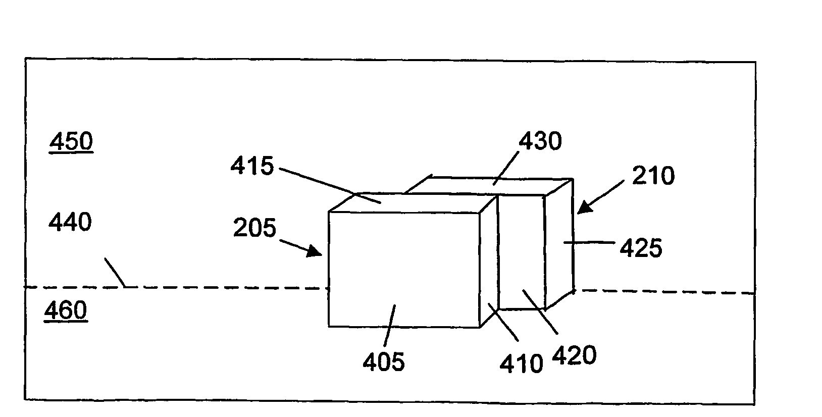
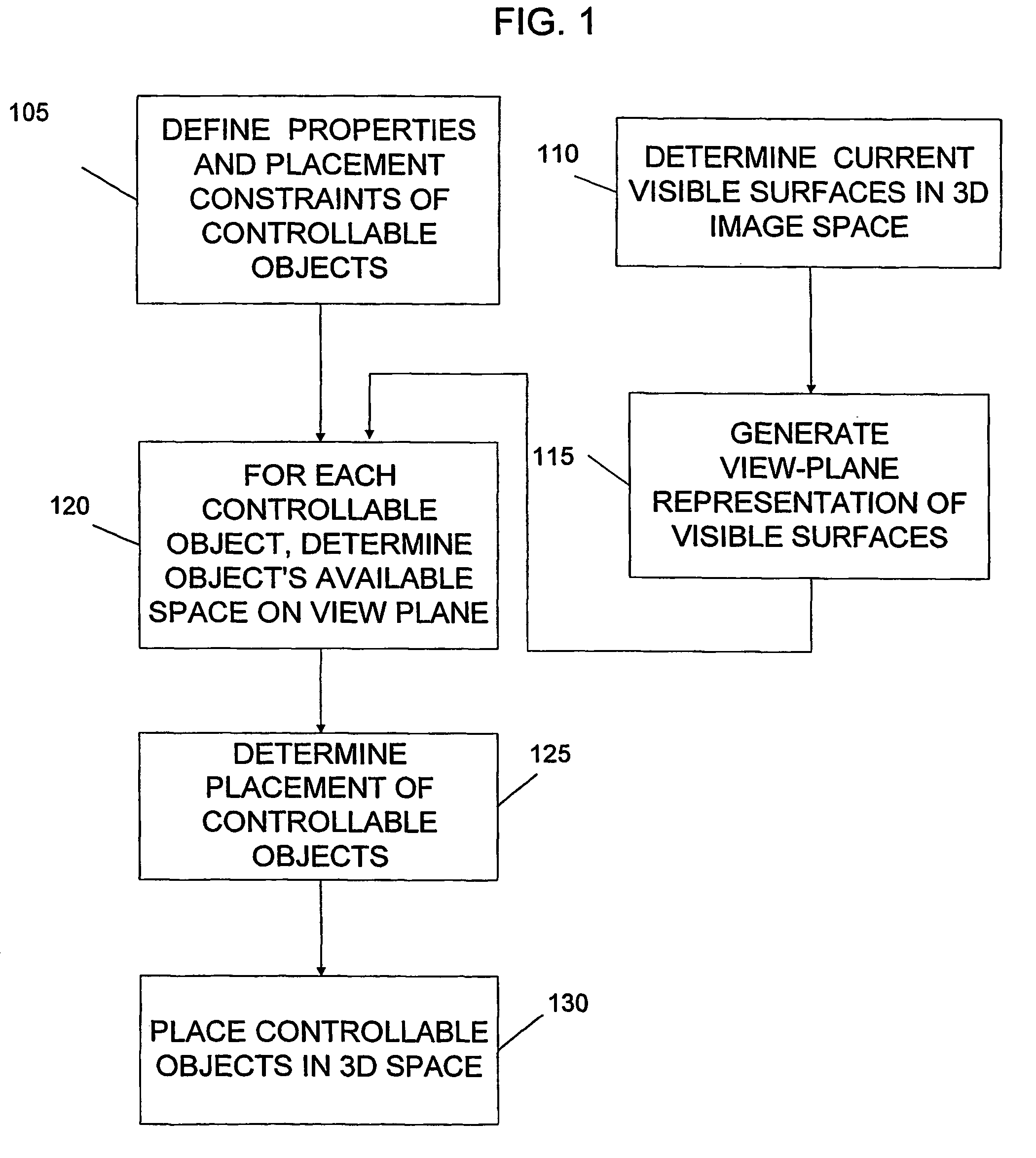
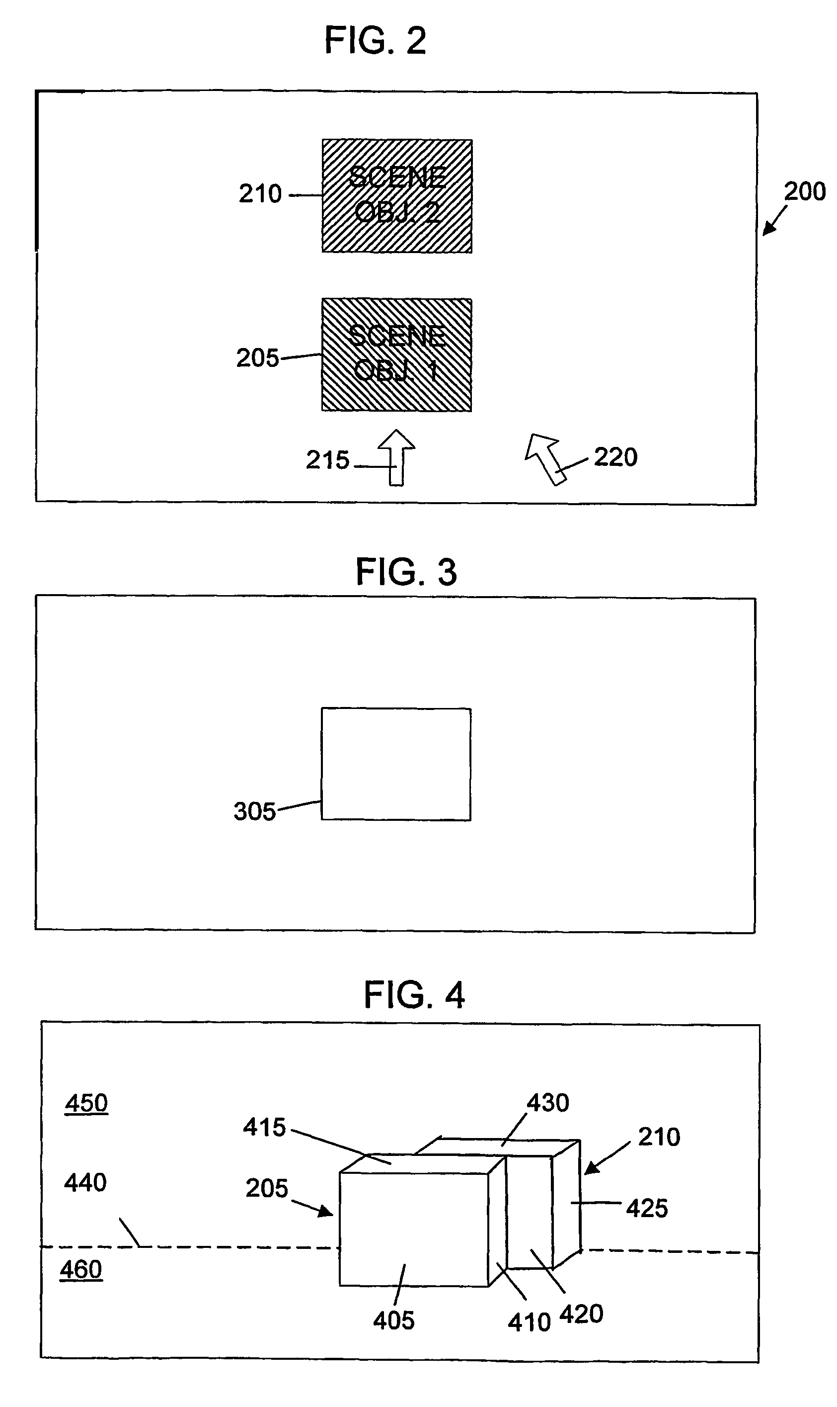
[0025]FIG. 1 is a flow chart illustrating an overview of a method of 3D view management for a current frame of a 3D scene in accordance with the present invention. A 3D image of a frame of a scene or object is to be generated in a conventional manner. The 3D image can be displayed in a number of ways which are well known in the art, such as a conventional 2D display device, such as a CRT or LCD screen, stationary, non-stationary, handheld, or head-worn displays for virtual reality or augmented reality applications, including head tracked display devices, and the like. In 3D rendering, objects having defined properties of size, position, opacity, and the like are placed in the 3D virtual space and are rendered in perspective from a particular view point. Based on the view point of the user and the properties of the objects in the 3D virtual space, referred to herein as scene objects, certain surfaces of the scene objects will be visible, while others are occluded by other scene objec...


PUM


Abstract

A method for managing a display space for a 3D environment is provided. A 3D scene having at least one scene object (105) is displayed and the visible surfaces (110) of the scene objects are represented as visible space in a 2D view plane representation. Controllable objects that are to be placed in the scene are defined by parameters such as size, placement priority, proximity relationships and the like. The available space for placing controllable objects, which can include empty space and low priority background and foreground regions, is determined for each controllable object. The placement (125) for controllable objects in the 3D space is then determined in accordance with at least placement parameter and one of the visible space and available space of the view-plane representation (120) such that view management objectives, such as not occluding important scene objects, are accomplished.

Description

CLAIM FOR PRIORITY TO RELATED APPLICATIONS[0001]This application claims the benefit of U.S. Provisional Patent Application Ser. No. 60 / 291,798, filed on May 17, 2001, entitled View Management For Virtual And Augmented Reality, which is hereby incorporated by reference in its entirety.STATEMENT OF GOVERNMENT RIGHTS[0002]The present invention was made in part with support from the National Library of Medicine, Grant No. 5-R01 LM06593-02 and the Office of Naval Research, Contract Nos. N00014-99-1-0683, N00014-99-1-0249 and N00014-99-1-0394. Accordingly, the United States government may have certain rights to this invention.FIELD OF THE INVENTION[0003]The present invention relates generally to three dimensional imaging and more particularly relates to a system and method for managing the placement of controllable objects in a three dimensional projection.BACKGROUND OF THE INVENTION[0004]Computer graphics systems which are commonly used today generally provide a representation of the wor...

Claims


Application Information

Patent Timeline
Patent Type & Authority Patents(United States)
IPC IPC(8): G06T15/00G06T15/40G06T19/00G09G1/06G09G5/00
CPCG06T15/40G06T19/20G09G3/003G09G1/06G06T2219/2004
Inventor BELL, BLAINE A.FEINER, STEVEN K.HOELLERER, TOBIAS H.
Owner THE TRUSTEES OF COLUMBIA UNIV IN THE CITY OF NEW YORK
Learn More