Passive NFC activation of short distance wireless communication

a wireless communication and passive technology, applied in the field of mobile terminals, can solve the problems of increasing the activation/connection reducing the standby time of the mobile terminal, and consuming power, and achieve the effect of reducing the connection tim

Active Publication Date: 2010-01-05
SONY CORP
View PDF26 Cites 72 Cited by
  • Summary
  • Abstract
  • Description
  • Claims
  • Application Information

AI Technical Summary

Benefits of technology

[0013]Additionally, the scanning includes a high frequency scan to decrease connection time.

Problems solved by technology

In these different scanning schemes, each scan consumes power, which decreases the standby time of the mobile terminal.
This increase, however, leads to a longer activation / connection time.

Method used


Image

  • Passive NFC activation of short distance wireless communication
  • Passive NFC activation of short distance wireless communication
  • Passive NFC activation of short distance wireless communication

Examples


example

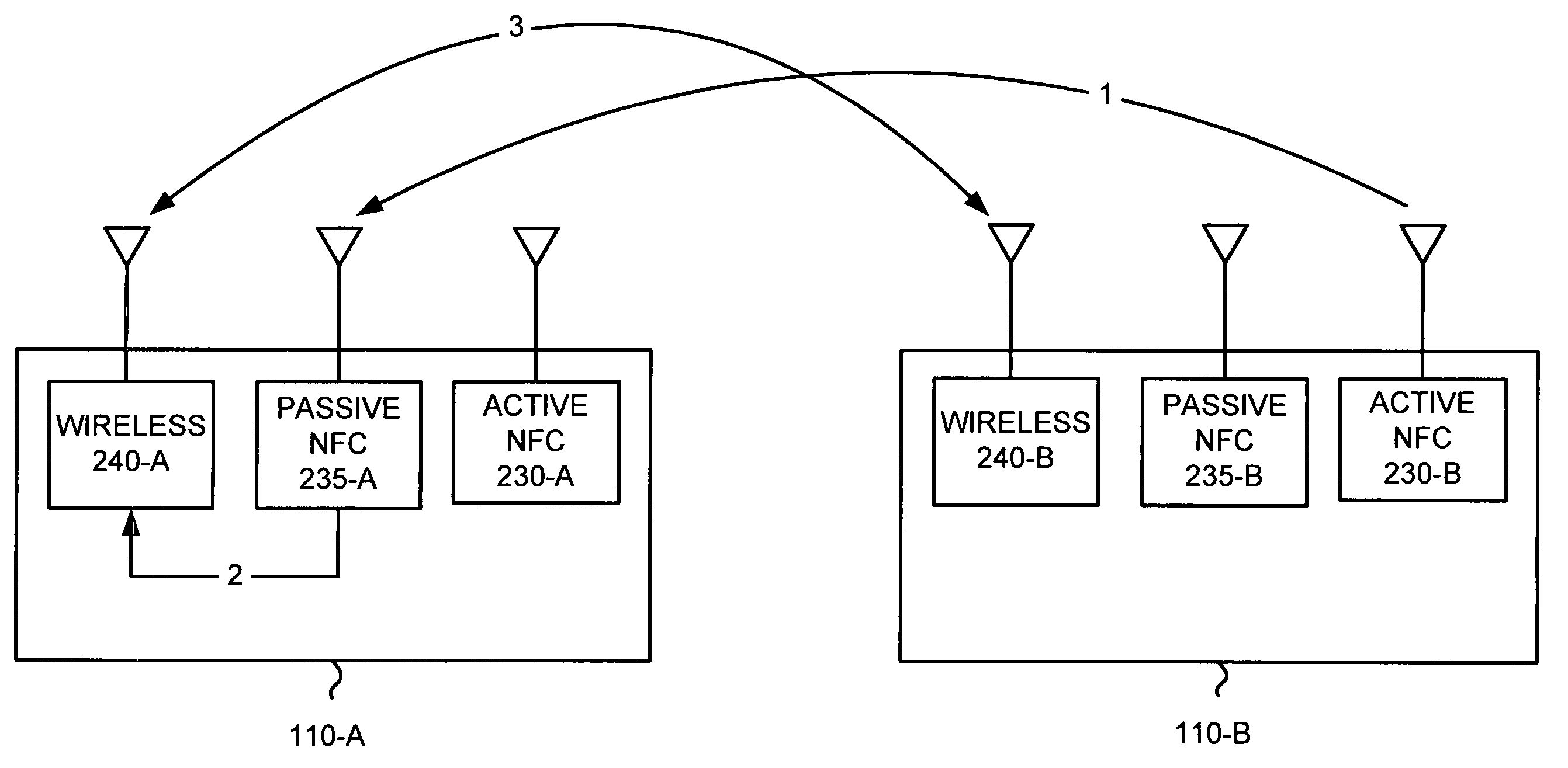
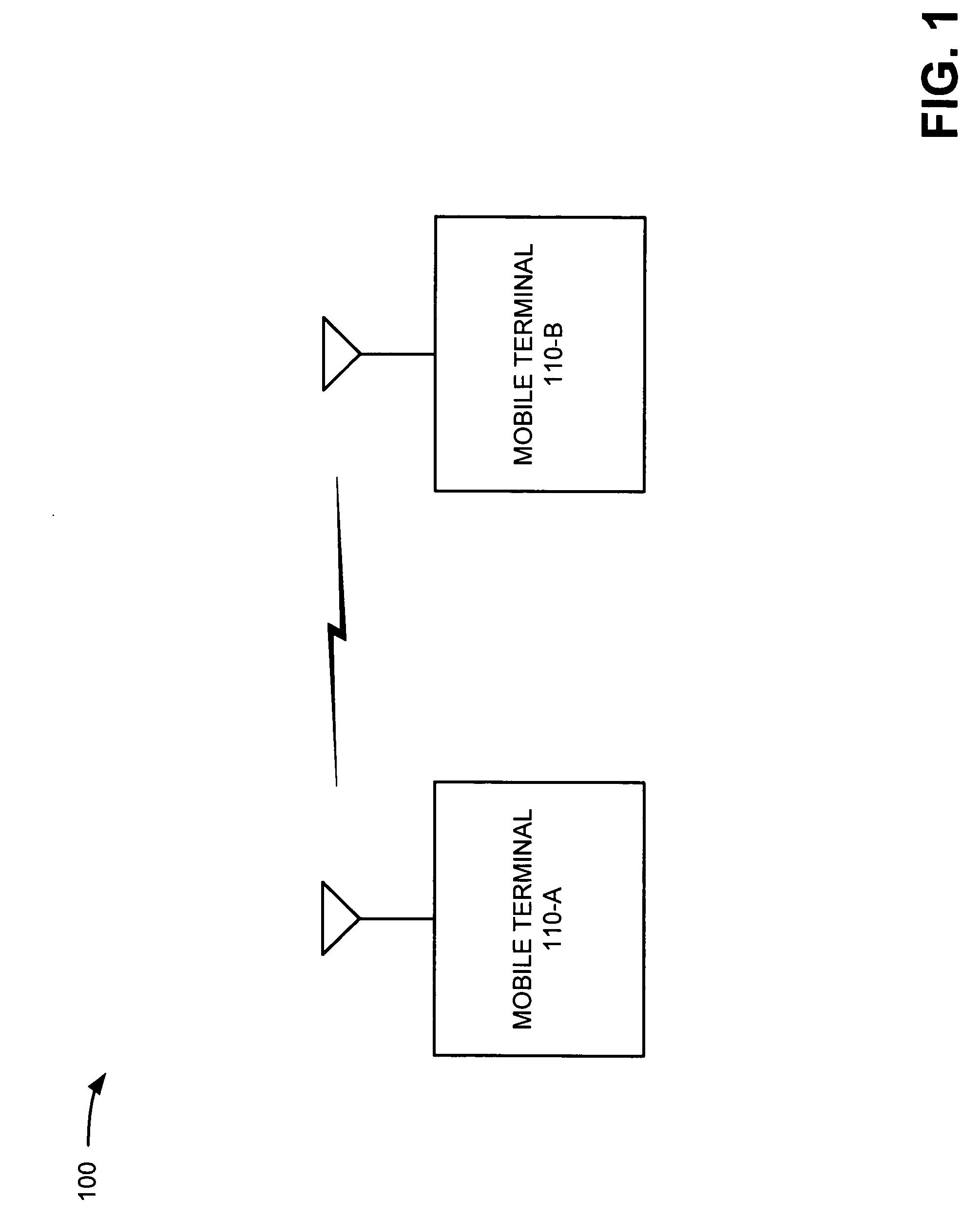
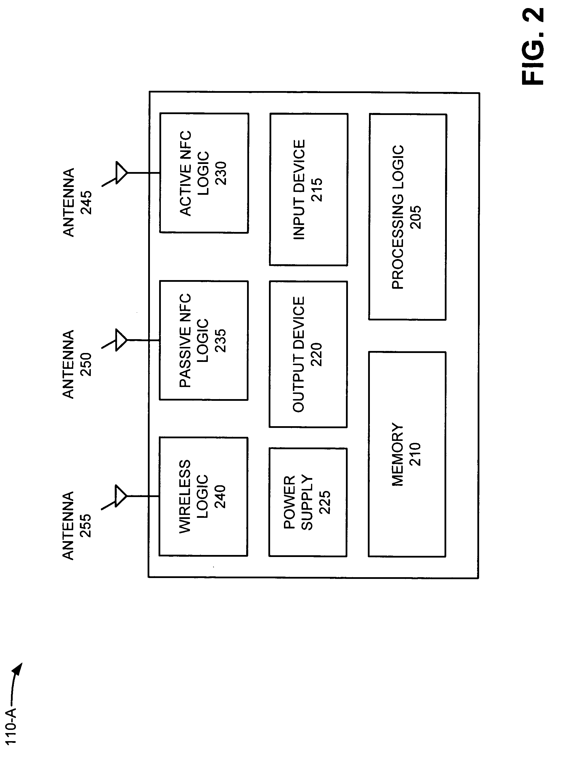
[0051]The following example illustrates the above processing. FIG. 4 is an exemplary diagram of the processing described with respect to FIG. 3. Assume, for this example, that mobile terminal 110-B wants to establish a wireless connection with mobile terminal 110-A. The processing of FIG. 4 may begin with mobile terminal 110-B transmitting an activation signal (signal 1), via active NFC logic 230-B, to mobile terminal 110-A. Prior to receiving the activation signal, mobile terminal 110-A may operate in a low power (or nearly no power) mode. In this mode, scanning may be deactivated in mobile terminal 110-A and no power may be devoted to active NFC logic 230-A, passive NFC logic 235-A (which does not require power), and wireless logic 240-A.

[0052]Mobile terminal 110-A may receive the activation signal via passive NFC logic 235-A. Passive NFC logic 235-A may draw power from the activation signal to wake up wireless logic 240-A (signal 2). In response, wireless logic 240-A may, for exa...


PUM


Abstract

A mobile terminal includes a passive wireless receiver and a wireless transceiver. The passive wireless receiver receives a first activation signal from another mobile terminal, and transmits a second activation signal using power from the first activation signal. The wireless transceiver receives the second activation signal, and establishes a wireless connection with the other mobile terminal in response to receiving the second activation signal.

Description

BACKGROUND[0001]1. Technical Field of the Invention[0002]Implementations described herein relate generally to mobile terminals and, more particularly, to using passive near field communication (NFC) to activate a mobile terminal for wireless communications.[0003]2. Description of Related Art[0004]Several short distance wireless communication protocols, such as Bluetooth and IEEE 802.11 (wireless local area network or WLAN) exist that allow for two wireless devices, such as mobile terminals, to communicate. Different scanning schemes are used to adapt to changes in the ad-hoc networks that are created between these wireless devices. In these different scanning schemes, each scan consumes power, which decreases the standby time of the mobile terminal. To decrease the power consumption associated with these scans, the time between each scan can be increased. This increase, however, leads to a longer activation / connection time.SUMMARY[0005]According to one aspect, a method, performed by...

Claims


Application Information

Patent Timeline
Patent Type & Authority Patents(United States)
IPC IPC(8): H04B7/00H04W8/00H04W48/16H04W52/02
CPCH04B5/0037H04B5/02Y02B60/50H04W48/16H04W52/0261H04W8/005Y02D30/70
Inventor LJUNG, PETER
Owner SONY CORP
Why Eureka
Try Eureka