Curtain to direct crop in a header

a header and cutterbar technology, applied in the field of harvesting machines, can solve the problems of crop movement between cutterbars and transverse conveyance/consolidation apparatuses, crop productivity loss, seed loss,

Active Publication Date: 2010-01-12
BLUE LEAF I P INC
View PDF24 Cites 13 Cited by
  • Summary
  • Abstract
  • Description
  • Claims
  • Application Information

AI Technical Summary

Benefits of technology

[0006]Accordingly, it is an object of the present invention to provide a specialty crop harvesting header which efficiently gathers severed crop from a cutterbar and conveys it to a discharge zone and there deposits the crop evenly to form a uniform windrow.
[0007]It is a further object of the present invention to provide a crop harvesting header having an additional transversely arranged curtain for directing severed crop material into a transverse crop converging apparatus without undue disturbance of specialty crops which could damage the crop.
[0008]It is a further object of the present invention to provide a transverse curtain to smooth severed crop material and direct it into an transverse crop conveyance mechanism for optimal movement toward a central discharge zone in a header.

Problems solved by technology

Clogs result in lost harvesting productivity while an operator removes the entangled crop and also lost seed due to the increased disruption to the crop material when the entanglement begins.
While a forward debris skirt is known for managing crop movement into the header and toward the cutterbar apparatus, crop movement between the cutterbar apparatus and the transverse conveyance / consolidation apparatus remains problematic.
Additionally, air flow generated by the conveyor or apparatus or conditioning rolls, if present, tends to move in a forward direction counter to the rearwardly moving cut crop, which can disrupt crop flow within the header.

Method used


Image

  • Curtain to direct crop in a header
  • Curtain to direct crop in a header
  • Curtain to direct crop in a header

Examples


first embodiment

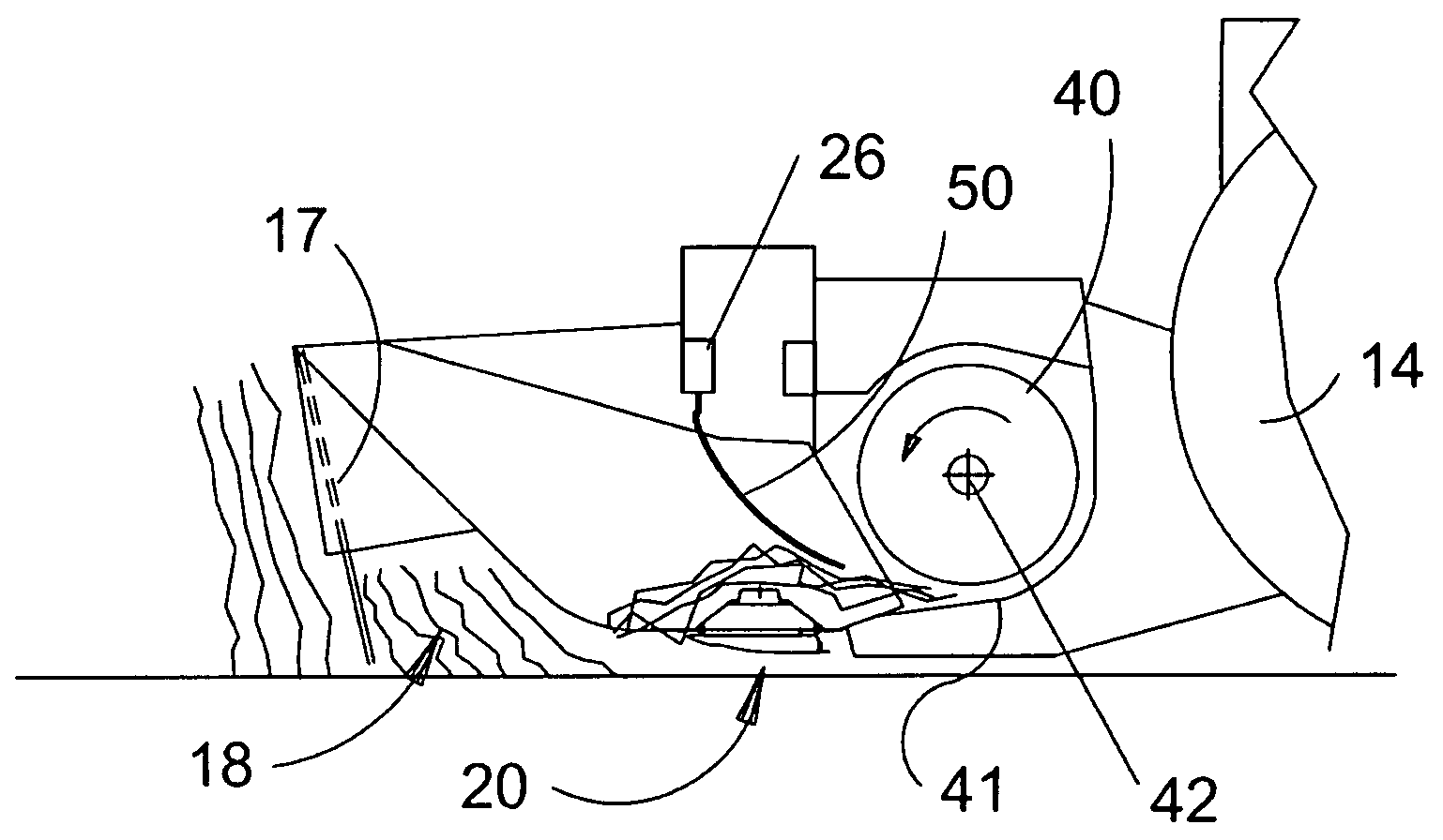
[0033]Finally, referring to FIG. 4, operation of header 12 with crop directing curtain 50 is illustrated. In a first embodiment, header 12 is propelled across a field of standing crop. The crop first encounters forward skirt 17 as the intake area 18 moves over the crop. Forward skirt 17 bends the crop to align it for severing by cutterbar 20. Standing crop spans the entire width of the header at this position. As the crop is severed from the ground by cutterbar 20, it continues rearward movement, relative to the header, toward transverse crop conveyor 40, which is a rotating auger in the preferred embodiment. The direction of auger rotation is indicated by an arrow in FIG. 4. In order to prevent severed crop material from moving upward and engaging the auger at a point above its rotational centerline 42 where the crop material is likely to clog or jam in the auger, the surface of curtain 50 directs the severed crop toward the lower forward portion of the auger so that the severed cr...

second embodiment

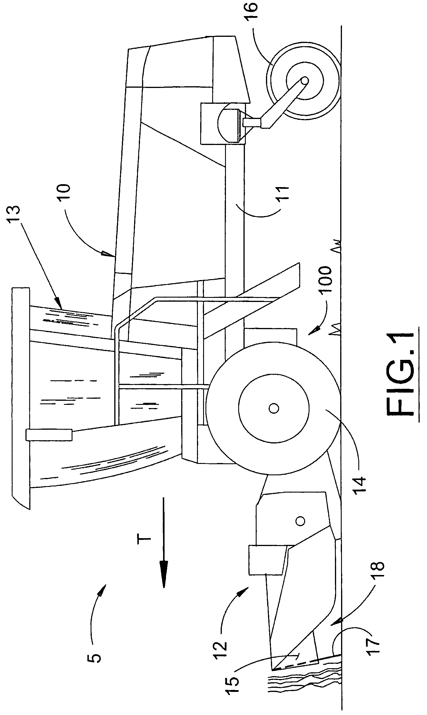
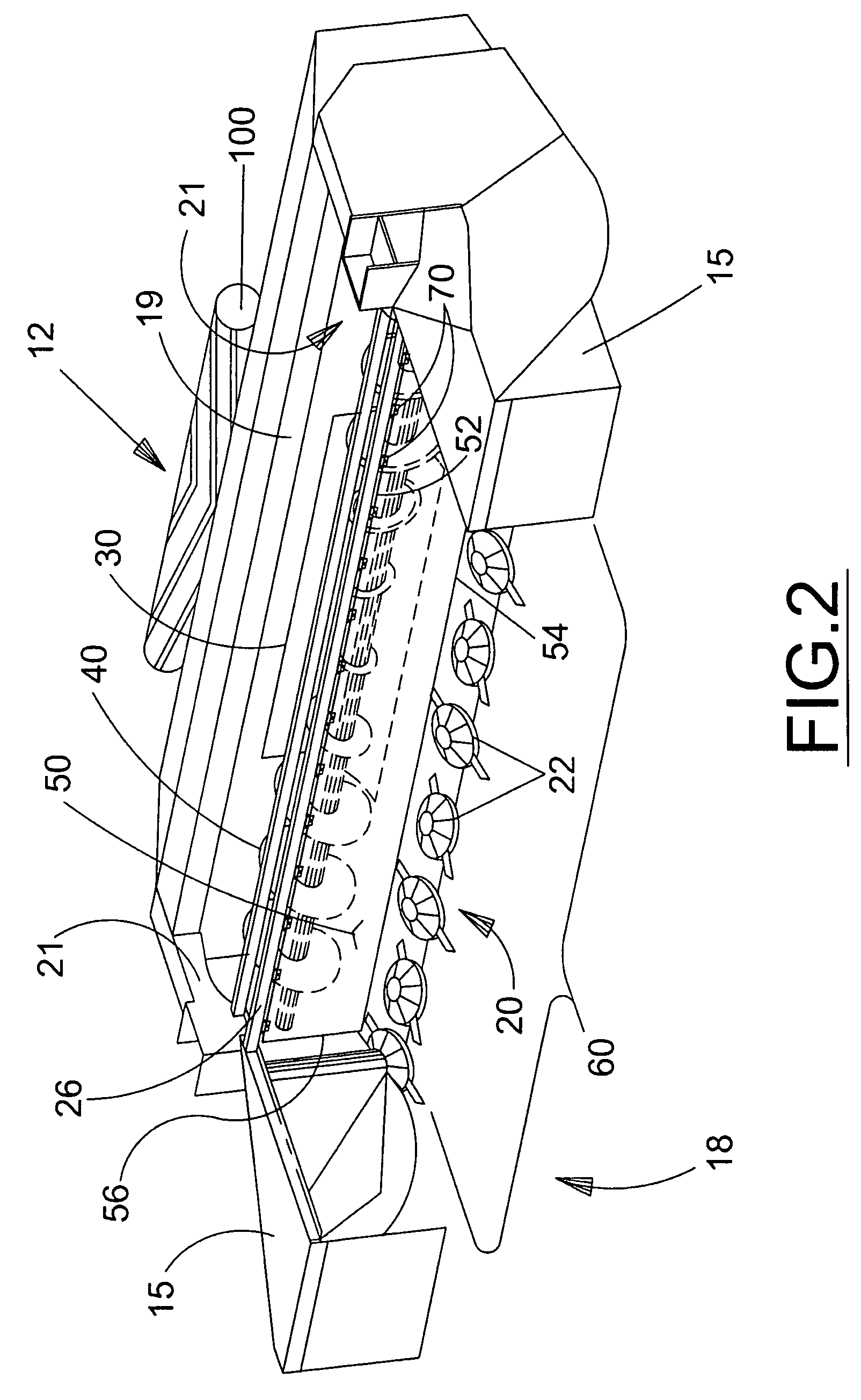
[0034]In a second embodiment, transverse crop conveyor 40 may or may not be present, but a conditioner apparatus 100 is positioned (see FIGS. 1 and 2) rearwardly from the header discharge opening 30. Operation of conditioners is well known and not discussed further in detail. Roll-type conditioners generate substantial air flow directed toward the front of the header in a direction that is opposite to that of the crop material being fed rearwardly toward the conditioner apparatus 100. The placement of curtain 50 in this embodiment limits the interaction of the forward flow of air with the cut crop material thereby allowing the cut crop material to continue its rearward movement more efficiently.

[0035]Curtain 50 is preferably formed from a flexible material such as reinforced rubber fabric to enable the curtain to conform to the contours of the passing crop material. Curtain 50 preferably comprises a single panel; however, those skilled in the art will recognize that identical functi...


PUM


Abstract

A curtain for directing severed crop movement in a cutting header in an agricultural harvester. The curtain optimizes crop movement between a cutterbar to a crop conveying auger for lateral movement of the crop material from outboard ends of the cutting header toward an interior discharge zone for formation of a windrow. The curtain also reduces the tendency for clogging that occurs when crop approaches conveying augers on both sides of an axial centerline by directing all crop material toward the trailing side of the rotating auger and by preventing airflow generated by the auger from disrupting crop approaching the auger. Crop smoothing by the curtain also reduces disturbances to the crop material during movement within the header which reduces seed loss in seed-bearing specialty crops.

Description

BACKGROUND OF THE INVENTION[0001]This invention relates generally to a machine for harvesting crops in a field and forming a windrow of cut crop, more particularly, to a curtain for managing crop flow coming off of the cutterbar and directing it into the header for subsequent crop processing.[0002]In modern crop harvesting machines, it is desirable to optimize cutting headers for specific crops in order to maximize harvesting efficiency. Such optimized headers are typically based on existing header designs with specific-purpose modifications incorporated to alter finite portions of the crop flow within the header to suit the specific crop being harvested. This approach helps control production costs of the equipment and extends the life cycle of a basic header design.[0003]One specific application involves harvesting of grasses, seed or other specialty crops having seeds on a stem which must be cut and dried in a windrow a desired amount before undertaking operations to separate the...

Claims


Application Information

Patent Timeline
Patent Type & Authority Patents(United States)
IPC IPC(8): A01D34/00A01D43/00
CPCA01D41/14
Inventor DIEDERICH, JR., ANTHONY F.BLAKESLEE, EDWARD A.THAXTON, WAYNE D.
Owner BLUE LEAF I P INC
Why Eureka
Try Eureka