
Method for surface blasting cavities, particularly cavities in gas turbines

a gas turbine and cavity technology, applied in the field of gas turbine cavities, can solve the problems of large limitations, reduced ductility of material in the area of through-going bore holes, and high demands on the rotor of the machine, so as to reduce the danger of material damage, and minimize the deformation area of the cavity. effect of the area

Inactive Publication Date: 2010-01-12
MTU AERO ENGINES GMBH +1
View PDF44 Cites 16 Cited by
  • Summary
  • Abstract
  • Description
  • Claims
  • Application Information

AI Technical Summary

Benefits of technology

[0006]Through the inventive acceleration of the shot balls used for the blasting with the aid of a vibrator, a random motion direction of the shot balls arises due to multiple reflections, whereby material deformations in the area of the cavities are minimized. Furthermore, a temporally smaller impulse or momentum density arises due to the smaller number of the utilized shot balls, whereby similarly the danger of material damages is reduced. In order to provide a momentum sufficient for the surface hardening despite the reduced temporal momentum density, shot balls with an adapted diameter, a higher density and therewith ultimately a greater mass are used.

Problems solved by technology

During the operation of a gas turbine, especially the rotors thereof are subject to high demands.
If, for example, the surfaces of through-going bored holes are to be hardened with the aid of shot balls accelerated by an airstream or a centrifuge, the problem arises, that especially corners or transition areas of the through-going bored holes between a surface of the rotor and an inner surface of the through-going bored holes are subjected to a strong plastic material deformation, whereby the ductility of the material in the area of the through-going bored holes can be reduced and thus disadvantageously influenced.
The methods for the surface blasting known from the state of the art are thus suitable only with great limitations for the treatment of cavities with especially tight cross-sectional areas.

Method used


Image

  • Method for surface blasting cavities, particularly cavities in gas turbines
  • Method for surface blasting cavities, particularly cavities in gas turbines
  • Method for surface blasting cavities, particularly cavities in gas turbines

Examples


Embodiment Construction

[0016]In the following, the present invention will be described in greater detail with reference to FIGS. 1 to 6.

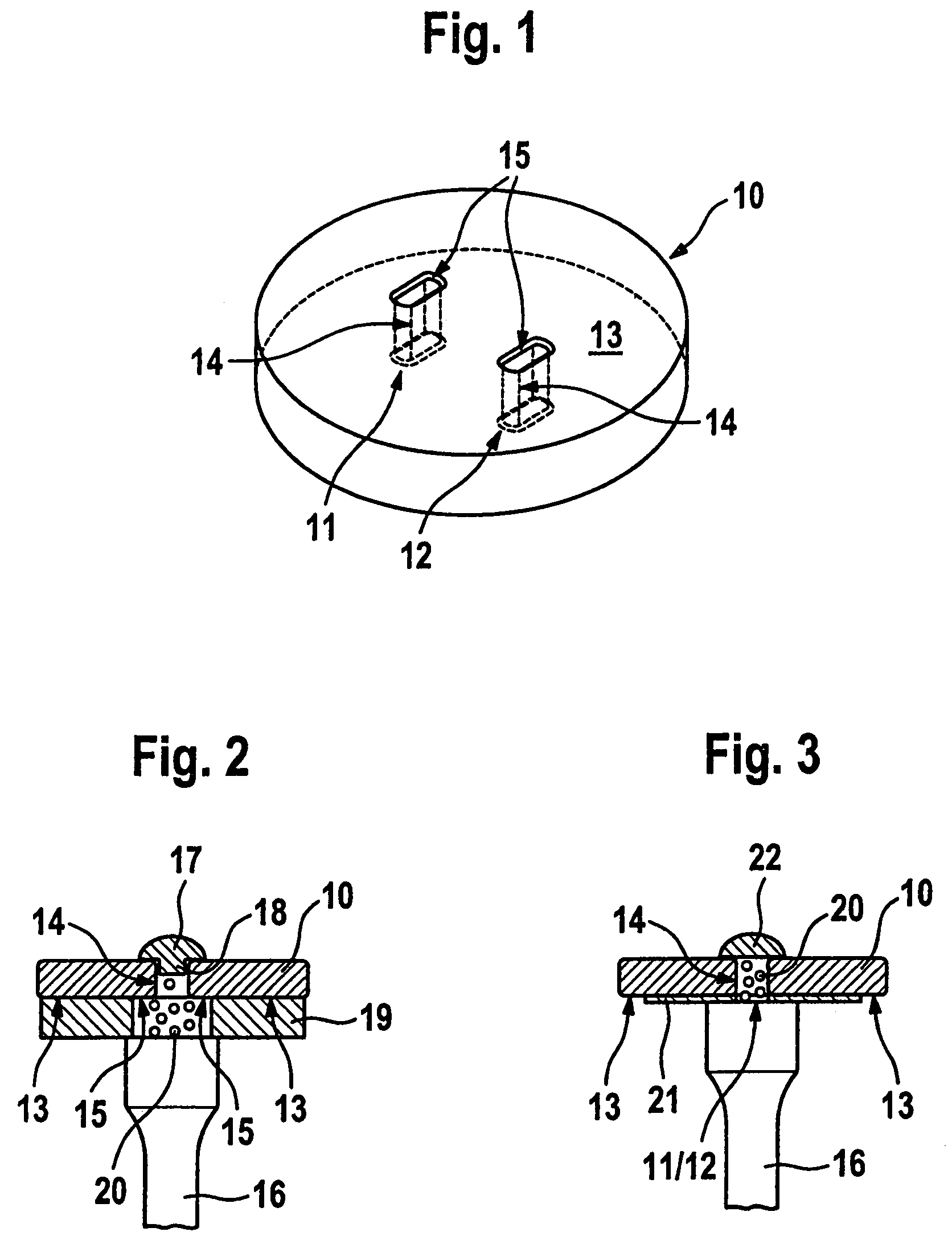
[0017]FIG. 1 shows a disk-shaped embodied component 10 with two through-going bored holes 11 and 12. The through-going bored holes 11 and 12 are bored holes with a relatively small cross-sectional area, especially with a cross-sectional area of 5 mm2 to 100 mm2. In the example embodiment of the FIG. 1, one shall begin from the point that the through-going bored holes 11, 12 comprise an oval cross-sectional area with a length of 3.8 mm and a width of 1.2 mm. Already from this it follows that the dimensions of the through-going bored holes 11, 12 are very small.

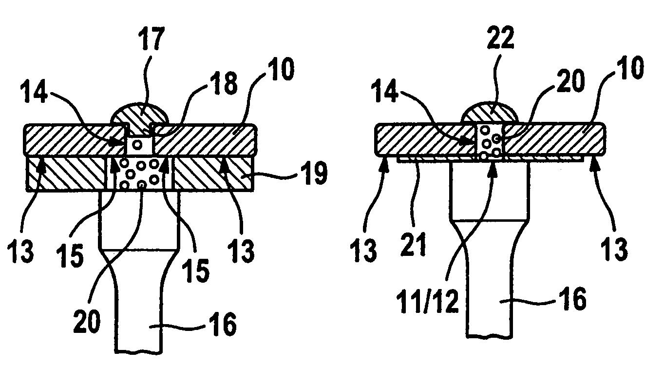
[0018]With the present invention, a method is now proposed, to densify or harden especially hollow spaces or cavities with such small dimensions, on their surfaces, by shot blasting. For this purpose, in the sense of the present invention, the shot balls are accelerated with the aid of at least one ultrasonic vibrato...


PUM

PropertyMeasurementUnit
Diameteraaaaaaaaaa
Diameteraaaaaaaaaa
Diameteraaaaaaaaaa

Abstract

In a method for surface blasting hollow spaces or cavities, especially cavities of gas turbines, shot balls are accelerated with the aid of at least one vibrator, whereby the ultrasonically accelerated shot balls are directed onto surfaces of a cavity that is to be blasted. The vibrator is preferably positioned with a small spacing distance, preferably on the order of magnitude of the diameter of the shot balls utilized for the blasting, from the cavity to be blasted.

Description

FIELD OF THE INVENTION[0001]The invention relates to a method for the surface blasting of hollow spaces or cavities, especially cavities of gas turbines.BACKGROUND INFORMATION[0002]Gas turbines, especially aircraft engines, have at least one rotor equipped with rotating runner or rotor blades especially in the area of a compressor as well as a turbine, whereby the rotor blades are increasingly embodied as an integral component of the rotor. Integral bladed rotors are also designated as “blisk” (bladed disk) or “bling” (bladed ring). Generally, through-going bored holes, extending in the radial direction, for fluids, for example oil, are generally integrated in such rotors. Such through-going bored holes are also designated as “bleed holes” and represent hollow spaces or cavities with small cross-sectional areas. Other bored holes extend in the axial direction and often serve for the screwing connection, whereby these bored holes similarly represent highly loaded zones or areas of co...

Claims


Application Information

Patent Timeline
IPC IPC(8): B23P15/00B24C1/00
CPCB24C1/10B24C5/005Y10T29/479
Inventor HOFFMANN-IVY, STEPHENCHEPPE, PATRICKDUCHAZEAUBENEIX, JEAN-MICHELBAYER, ERWIN
Owner MTU AERO ENGINES GMBH
Learn More